background image

Installation and Operational Instructions for ROBA

®

-diskstop

®


Type 894.5_ _._ _  Size 10


(B.8.4.5.EN)


23/03/2017 TK/TL/GC/SU


Chr. Mayr GmbH + Co. KG


Eichenstraße 1, D-87665 Mauerstetten, Germany


Tel.: +49 8341 804-0, Fax: +49 8341 804-421


Page 3 of 16 

www.mayr.com

, E-Mail: 

[email protected]


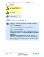
Safety Regulations 

These Safety Regulations are user hints only and may not be complete!


General Guidelines 

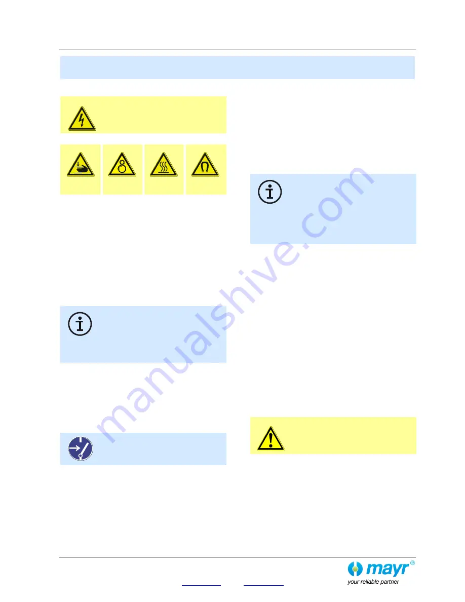
DANGER 

Danger of death!  
Do not touch voltage-carrying cables and 
components. 

Brakes may generate further risks, among other things: 

Hand injuries 


Danger of 

seizure 

Contact with 
hot surfaces 

Magnetic 

fields 


Severe injury to people and damage to objects may result if:


  the electromagnetic brake is used incorrectly. 

  the electromagnetic brake is modified. 

  the relevant standards for safety and / or installation 

conditions are ignored. 

During the required risk assessment when designing the  
machine or system, the dangers involved must be evaluated and  
removed by taking appropriate protective measures. 

To prevent injury or damage, only specialist personnel are 
allowed to work on the components.


They must be familiar with the dimensioning, transport, 
installation, inspection of the brake equipment, initial operation, 
maintenance and disposal according to the relevant standards 
and regulations. 

Before product installation and initial operation, 
please read the Installation and Operational 
Instructions carefully and observe the Safety 
Regulations. Incorrect operation can cause injury 
or damage. At the time these Installation and 

Operational Instructions go to print, the electromagnetic brakes 
accord with the known technical specifications and are 
operationally safe at the time of delivery. 

  Technical data and specifications (Type tags and 

documentation) must be followed. 

  The correct connection voltage must be connected according 

to the Type tag and wiring guidelines. 

  Check electrical components for signs of damage before 

putting them into operation. Never bring them into contact 
with water or other fluids. 

  Please observe the EN 60204-1 requirements for electrical 

connection when using in machines. 


Only carry out installation, maintenance and 
repairs in a de-energised, disengaged state 
and secure the system against inadvertent 
switch-on. 


Guidelines for Electromagnetic Compatibility 
(EMC) 

In accordance with the EMC directives 2014/30/EU, the 
individual components produce no emissions. However, 
functional components e.g. mains-side energisation of the 
brakes with rectifiers, phase demodulators, ROBA

®

-switch 

devices or similar controls can produce disturbance which lies 
above the allowed limit values. For this reason it is important to 
read the Installation and Operational Instructions very carefully 
and to keep to the EMC directives. 
 

Application Conditions 

The catalogue values are guideline values which 
have been determined in test facilities. It may be 
necessary to carry out your own tests for the 
intended application. When dimensioning the 
brakes, please remember that installation 

situations, braking torque fluctuations, permitted friction work, 
bedding-in condition / conditioning of the brake linings and 
wear as well as general ambient conditions can all affect the 
given values. These factors should therefore be carefully 
assessed, and alignments made accordingly. 

  Mounting dimensions and connection dimensions must be 

adjusted according to the size of the brake at the place of  
installation. 

  Use of the brake in extreme environmental conditions or 

outdoors, directly exposed to the weather, is not permitted. 

  The brakes are designed for a relative duty cycle of 60 %. A 

duty cycle > 60 % leads to higher temperatures, which cause 
premature ageing of the noise damping and therefore lead to 
an increase in switching noises. Furthermore, the switch 
function of the release monitoring can be impaired.  
The max. permitted switching frequency is 180 1/h. 
These values are valid for intermittent periodic duty S3 60 %. 
The permitted surface temperature on the mounting surface


must not exceed 80 °C at a max. ambient temperature of  
40 °C. 

  The braking torque is dependent on the current bedding-in 

condition of the brake. Bedding in / conditioning of the friction 
linings is necessary. 

  The brakes are only designed for dry running. The torque is 

lost if the friction surfaces come into contact with oil, grease, 
water or similar substances or any other foreign bodies. 

  The surfaces of the outer components have been 

phosphated manufacturer-side to form a basic corrosion 
protection. 

CAUTION 

The friction linings may rust up and seize up in 
corrosive ambient conditions and / or after 
longer downtimes. 
The user is responsible for taking appropriate 
countermeasures. 


Содержание WGG-29.1

Страница 1: ...Subject to changes without notice Subject to changes without notice EN EN Gearless Lift Machines WSG WGG 29 1 WSG WGG 29 2 WSG WGG 29 3 Reprinting translation or reproduction in any form whether in pa...

Страница 2: ...operating instructions are applicable to lift machines WSG WGG 29 1 WSG WGG 29 2 WSG WGG 29 3 WITTUR Electric Drives GmbH reserves the right to correct or change the contents of this manual and these...

Страница 3: ...tion Winding protection Separately driven fan 10 4 2 3 Speed Position measuring system 12 4 2 4 Brake 13 5 Commissioning 16 6 Operation and maintenance 17 6 1 General 17 6 2 Maintenance intervals 17 6...

Страница 4: ...ifts They may only be used for their intended purpose and with all safety devices in proper working order They may only be operated under the conditions described in this manual and with due regard to...

Страница 5: ...brake after installing the machine Repairs may only be carried out by the manufacturer or an authorised repair agency Unauthorised opening and tampering may result in injuries to persons and property...

Страница 6: ...hich can be used to prevent uncontrolled upward movement of the car The nameplate of the lift machine is on the motor frame 3 Product overview Type code of lift machine Rated voltage Rated speed Rated...

Страница 7: ...C Do not store lift machines in the open air Bright parts are not sufficiently preserved to withstand extended periods of exposure Avoid excessive storage periods recommendation max one year After pr...

Страница 8: ...frame or foundation loads before installing the lift machine Warning Cover the machine and especially the brakes when doing any machining or dust producing work in the shaft or machine room The measur...

Страница 9: ...ystem is properly isolated Before making any electrical connections check that the connecting cables are suitable for their specific application and for the relevant voltages and currents sufficiently...

Страница 10: ...ed in the winding such as PTC thermistor detectors and thermostatic switches must be evaluated in the control system or frequency inverter to protect the motor from overtemperature The separately driv...

Страница 11: ...ble at speeds less than or equal to the rated speed of the respective motor PTC thermistors The maximum operating voltage of the PTC thermis tors is not allowed to exceed 25 V DC To achieve the maximu...

Страница 12: ...ed cable to connect the measuring system to the inverter system We recommend the use of our cable sets which can be supplied as an accessory Caution The measuring system of WSG lift machines with a sy...

Страница 13: ...ng must also be performed from the AC side at the same time Wiring with a varistor as shown in the circuitry suggestion on page 15 Note on the use of DC AC side switching AC side switching is recommen...

Страница 14: ...cts clean Connection of the brakes The brake coils the brake control units and the monitoring contacts are connected to the mains in the brake terminal box Warning The microswitches must be evaluated...

Страница 15: ...for brake control WxG 29 Circuitry suggestion for brake control DC side switching and separate control of the partial brakes AC side switching and separate control of the partial brakes K1 and K2 mus...

Страница 16: ...Check the proper functioning of the temperature monitoring devices e g by interrupting the temperature monitoring circuit Check the brake connection and the proper functioning of the brake monitoring...

Страница 17: ...htening torques are observed see table Secure the bolts screws with omnifit 100 or a similar product against accidental loosening 6 2 Maintenance intervals Dimension Tightening torque Nm Strength clas...

Страница 18: ...years using a KP 2 N 30 to DIN 51 502 grease such as W lalit LZ 2 or Kl berlub BE 41 542 approx 205 g on DE and approx 55 g on NDE Use a conventional grease gun and press the grease into the hydraulic...

Страница 19: ...itched off as the rotating fan wheel could be dangerous Operation of the motor without filter mats is not permitted DE extraction of the grease NDE extraction of the grease Extraction of the grease Wi...

Страница 20: ...and the Bowden cables are available sepa rately If the brakes are released manually the lift car moves in the direction of the higher weight The motor winding should be short circuited using the motor...

Страница 21: ...emer gency evacuation Take particular care to remove the lever extensions and all parts of the mechanical return motion device Mechanical return motion device For cases such as lift failure or the car...

Страница 22: ...es must be kept open separately even if the safety circuit is open This should be done using suitable electric circuitry or by hand This state must not be maintained in the long term Observe the lift...

Страница 23: ...asuring system The measuring system is only accessible from the rear side of the motor See the mounting instructions for the Heidenhain encoder Disassemble the measuring system only if this is necessa...

Страница 24: ...ge too low Brake shoes mechanically blocked Overexcitation rectifier defective Check electrical connection Check braking voltage supply voltage Remove mechanical blocking Replace overexcitation rectif...

Страница 25: ...0 suitable for inverter supply using a link voltage of 500 620 V DC X3 X4 Rated speed e g 11 118 min 1 with DT 650 mm v 2 0 m s suspension 2 1 17 176 min 1 with DT 650 mm v 3 0 m s suspension 2 1 29...

Страница 26: ...D 10 Brake torque 2 3 x 4600 Nm optionally adjustable 30 Air gap sB 0 5 0 1 0 15 mm new air gap Max air gap sB max 0 7 mm Holding voltage 103 V DC Holding current 2 3 x 1 0 A Overexcitation voltage 20...

Страница 27: ...0 Gearless Lift Machine WSG WGG 29 Operating Instructions Code GM 8 002662 EN Date 04 02 2019 Version 0 19 Page 27 Subject to changes without notice Subject to changes without notice EN 9 Dimension dr...

Страница 28: ...commended encoder system recommended measurement system cable E Pack Arkel ARCODE ECN 1313 EnDat or SSI 503 325 021 xx D Pack Arkel ADrive CT unidrive SP ECN 1313 EnDat or SSI 502 452 021 xx Fuji Fren...

Страница 29: ...without notice Subject to changes without notice EN 10 2 Rope clamp A rope clamp is used for example to pull the car from the safety devices if the ropes are slipping Fasten the clamp to the traction...

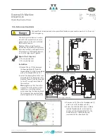
Страница 30: ...n Install the Bowden cables symmetrically Note the different configurations when using two or three brakes 9 1 7 8 2 2 brakes 3 brakes 8 8 Danger Lock the car and the counterweight and ensure that all...

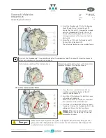
Страница 31: ...e 150 N with a 0 5 m lever length is unacceptable as it can damage the brakes beyond repair Set the lever 9 back to its original position once the test is completed check the air gap with the traction...

Страница 32: ...a fine thread M 36 x 1 5 2 Install the bearing block 8 as rec ommended in the drawing on the machine frame It can be mounted to the left or right hand side of the machine Warning Ensure that the safe...

Страница 33: ...will rotate anti clockwise Make sure that the nut 5 does not obstruct the movement of the slide block 8 3 If necessary the slide block 4 can be reposi tioned by inserting the threaded bolt 3 into a su...

Страница 34: ...19 Version 0 19 Page 34 Subject to changes without notice Subject to changes without notice EN 11 Special features of WGU 29 lift machines Danger The maximum permissible shaft load of the WGU 29 lift...

Страница 35: ...notice Subject to changes without notice EN 12 Spare parts Item Part Description Motor 01 traction sheave acc machine nameplate type code X5 X6 X7 02 Measuring system depending on spec ECN 1313 SSI 20...

Страница 36: ......

Страница 37: ......

Страница 38: ...center m DBS Diameter of the brake disk effectively m vBS Gliding speed on the brake disk diameter effectively m s i Ratio of the car suspension Maximum tripping speed gliding speed on the brake disk...

Страница 39: ...on The shaft itself has to be statically supported in two points The calculation evidence must be enclosed with the technical documentation of the lift 2 6 The setting of the brake force has to be sec...

Страница 40: ...d only Page 3 of 3 3 5 This EU type examination certificate was issued according to the following standards EN 81 1 1998 A3 2009 D Annex F 7 and F 8 EN 81 20 2014 D part 5 6 6 11 5 6 7 13 EN 81 50 201...

Страница 41: ...Co Chr Mayr GmbH Co KG of 2016 09 15 Page 1 of 1 Authorised Manufacturer of Serial Production Production Sites valid from 2017 01 18 Company Chr Mayr GmbH Co KG Address Eichenstr 1 87665 Mauerstetten...

Страница 42: ......

Страница 43: ......

Страница 44: ...times Contents Page 1 Contents Page 2 Safety and Guideline Signs Certification Guidelines on EU Directives Page 3 Safety Regulations Page 4 Safety Regulations Page 5 Safety Regulations Page 6 Brake I...

Страница 45: ...nditions but not in the overall system Guidelines on the Machinery Directive 2006 42 EC The product is a component for installation into machines according to the Machinery Directive 2006 42 EC The br...

Страница 46: ...tch on Guidelines for Electromagnetic Compatibility EMC In accordance with the EMC directives 2014 30 EU the individual components produce no emissions However functional components e g mains side ene...

Страница 47: ...the braking torque levels and the noise damping behaviour Intended Use This safety brake is intended for use in electrically operated elevators and goods elevators Furthermore this brake can be used a...

Страница 48: ...tive CSA C22 2 No 14 2010 Industrial Control Equipment UL 508 Edition 17 Industrial Control Equipment 2014 33 EU Elevator Directive EN 81 20 Safety rules for the construction and installation of lifts...

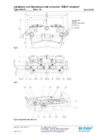
Страница 49: ...23 03 2017 TK TL GC SU Chr Mayr GmbH Co KG Eichenstra e 1 D 87665 Mauerstetten Germany Tel 49 8341 804 0 Fax 49 8341 804 421 Page 6 of 16 www mayr com E Mail info mayr com Fig 1 Fig 2 Fig 3 Fig 4 Fig...

Страница 50: ...ize 10 B 8 4 5 EN 23 03 2017 TK TL GC SU Chr Mayr GmbH Co KG Eichenstra e 1 D 87665 Mauerstetten Germany Tel 49 8341 804 0 Fax 49 8341 804 421 Page 7 of 16 www mayr com E Mail info mayr com Fig 6 Fig...

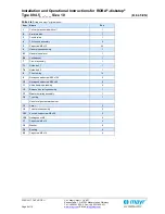
Страница 51: ...Counterplate 1 4 Friction pad assembly 4 5 Cap screw M6 x 12 24 6 Hand release assembly 1 6 1 Hand release lever 1 6 2 Lock washer 1 7 Carrier assembly 1 7 1 Guide bolt 1 1 7 2 Guide bolt 2 1 8 Thrus...

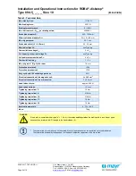
Страница 52: ...x PN Overexcitation time tO 1 2 s Max air gap a Fig 2 after wear 1 8 mm Protection electrical IP54 Protection mechanical IP10 Duty cycle with 180 switchings per hour 60 Electrical connection of the ma...

Страница 53: ...00 600 Drop out t 1 AC 1000 1000 2 Referring to the effective braking force 3 Referring to the nominal braking force The stated switching times can only be achieved using the respective correct electr...

Страница 54: ...ety brake function The ROBA diskstop brakes reliably and safely in the event of a power switch off a power failure or an EMERGENCY STOP Scope of Delivery State of Delivery The brakes are manufacturer...

Страница 55: ...gap between the friction lining and the side of the brake disk facing away from the screw on surface on the right and left hand sides and calculate the difference between the measurement values The d...

Страница 56: ...s the current to increase slowly as an exponential function Accordingly the build up of the magnetic field takes place more slowly and the braking torque drop curve 1 is also delayed Field Build up wi...

Страница 57: ...ge category acc IEC 60947 5 1 DC 12 resistance load DC 13 inductive load Wear Monitoring Item 13 Fig 5 Optional The ROBA diskstop brakes are supplied optionally with manufacturer side installed and ad...

Страница 58: ...Classification Hazardous property Attention H classification H372 Protective measures and rules of behaviour Do not inhale dusts Vacuum the dusts at the point of origin tested suction devices tested...

Страница 59: ...sible Causes Solutions Brake does not release Incorrect voltage on rectifier Rectifier failure Air gap too large worn friction lining Coil interrupted Incorrect rectifier e g normal rectifier without...

Отзывы: