background image

Gearless Lift Machine

WSG-08

with caliper disk brake

Operating Instructions

Seite/page

28

Datum/date

12.08.2016

Stand/version

0.18

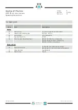
Fault

Possible cause

Remedy

Motor does not start, operates out of
control or develops no torque 

Motor not connected in proper

phase sequence

Measuring system not properly con-

nected

Converter parametrisation incorrect

EMC disturbance                              


Measuring system offset angle

incorrectly set

Measuring system defective

Connect motor correctly                     


Connect measuring system correctly   


Check converter parametrisation

Carry out shielding and earthing

measures as described by the convert-
er manufacturer

Check measuring system offset angle  


Replace measuring system

Motor noise

Bearing defective

Converter parametrisation incorrect

Notify customer service

Check converter parametrisation

Braking system does not release

Braking system is not supplied with

voltage

Brake magnet voltage too low

Brake shoes mechanically blocked 

Overexcitation rectifier defective

Check electrical connection

Check braking voltage supply voltage

Remove mechanical blocking

Replace overexcitation rectifier

Delay in braking system release

Overexcitation rectifier defective

Replace overexcitation rectifier

Braking system does not engage

Brake shoe mechanically blocked

Remove mechanical blocking

Delay in engaging of braking system 

Switch-off time too short with a.c.

side switching

Brake control using d.c. side switching

of the overexcitation rectifier

Brake makes loud switching noise

Brake air gap too large

D.c. side switching of the brake in

"normal operation"

Adjust brake air gap

Change over to brake control by a.c.

side switching in "normal operation"

Braking torque too low

Brake friction surface or brake lin-

ings dirty.

Foreign bodies between friction

surface and brake lining

Brake friction surface or brake lin-

ing have come into contact with
oily or greasy materials

Load torque too high

Clean friction surface / brake linings

Remove foreign bodies

Replace brake lining, clean brake

drum thoroughly

Reduce load torque 

9.11. Trouble shooting

Änderungen vorbehalten!                                                                                                                                                                                                                    Subject to changes without notice! 

Содержание Beamer 2 Series

Страница 1: ...ation or reproduction in any form whether in part or in full requires the prior written permission of WITTUR Holding GmbH Wittur Holding GmbH reserves the right to make changes in the information and pictures contained in these operating instructions without prior notice WITTUR Holding GmbH Rohrbachstraße 26 30 D 85259 Wiedenzhausen Germany Tel 49 0 81 34 18 0 Fax 49 0 81 34 18 49 http www wittur ...

Страница 2: ...e right to correct or change the contents of this manual and these product details without prior notice We expressly reserve the right to make technical changes which improve the lift machines or their safety stan dards without prior notice No liability can be accept ed for damage injuries or expense arising therefrom We cannot guarantee the correctness and complete ness of the details Offenburger...

Страница 3: ...9 5 Replacing the traction sheave 22 9 6 Replacing the brakes 23 9 7 Modification of brake arrangement WSG 08 1 3 24 9 8 Switch adjusting for monitoring the brake 25 9 9 Replacing the measuring system 26 9 10 Testing the brake system to EN 81 1 27 9 11 Trouble shooting 28 10 Type code 29 11 Technical data 30 12 Dimension drawing 31 13 Accessories 32 13 1 Connecting cable for measuring systems 32 1...

Страница 4: ...ulting from one or more of the following causes Improper use of the WSG 08 lift machine Improper installation commissioning operation or maintenance Operation of the WSG 08 with defective and or inop erative safety or protective devices Non compliance with the instructions contained in the operating instructions or other documentation sup plied Unauthorised construction modifications to the WSG 08...

Страница 5: ... system but are to be operated via an electronic frequency converter Direct connection to the mains may destroy the motor High surface temperatures may occur on the external parts of the machine There fore no temperature sensitive parts may be in contact with these parts or attached to them Protection against accidental contact should be provided if required The EC type examined fail safe brakes p...

Страница 6: ...eduction The bearings are sealed on both sides and life lubricated The main bearing has a provi sion for relubrication The drive specific measuring system 11 is located within the centre of the machine behind the ball bearing It is connected to the power supply by a signal plug connec tor 12 Within certain limits depending on the motor dimensions different measuring systems can be installed The el...

Страница 7: ...d 2 Laminated stator core 3 Magnet ring 4 Rotor 5 Traction sheave 6 Thread for return motion device 7 Shaft 8 Self aligning roller bearing 9 Ball bearing 10 Sinous spring 11 Measuring system ECN 1313 12 Measuring system connection 13 Motor connection 14 caliper disk brake 15 Brake connection 16 Ever plate 17 Example of brake top mounted 18 19 Rope slip off guards 20 21 Alternative locations for ro...

Страница 8: ...d to suspend additional loads Storage Store the motors only in closed dry dust free well ven tilated and vibration free rooms storage temperature 20 C to 60 C Do not store lift machines in the open air Bright parts are not sufficiently preserved to withstand extended periods of exposure Avoid excessive storage periods recommendation max one year After prolonged storage 3months rotate the motor in ...

Страница 9: ...bstructed i e sufficient heat dissipation by convection and radia tion must be ensured The torque and power values indicated in the Technical Data apply to the above ambient temperatures and alti tudes In case of a deviating altitude and or ambient temperature the reduction factors k shown in the diagram below must be used Mpermiss k MN Ppermiss k PN Fastening the machine The rope force can be app...

Страница 10: ...r of the energy recovery unit The maximum permissible rate of voltage rise dU dt at the motor terminals may be max 4 kV ms The overvoltage at the motor terminals must not exceed 1 56 kV It may be neces sary to use motor current filters or reactors to achieve these values 7 2 Motor connection Winding protection The electrical connection of the motor and the winding monitoring devices is made in the...

Страница 11: ...rrying capacity of PVC cables at a maxi mum ambient temperature of 40 C Handling the terminal strip Cable cross section Permissible max current r m s value Permissible max motor current IN S3 40 1 0 mm2 13 1A 20 7A 1 5 mm2 15 7A 24 8A 2 5 mm2 22 6A 35 7A 4 0 mm2 29 6A 46 7A 6 0 mm2 38 3A 60 5 A Note Motor connection diagram W1 V1 U1 2 1 M M 20 für Kabeldurchmesser 7 12 mm M 20 for cable diameter 7...

Страница 12: ...is provided on the motor frame for the connection of a protective or earth ing conductor as specified in VDE 0100 and VDE 0141 respectively When using shielded power cables make sure the cable shield metal contacts the motor frame over a large area This is achieved for example by special cable glands pro vided for shield contact Short circuiting The motor terminals of the synchronous lift machines...

Страница 13: ...cessories The measuring system of the WSG 08 lift machines is matched to the associated con verter Do not change the adjustment as this may make it impossible to use the motor On the measuring system housing there is a label showing the offset angle deter mined at the factory Note This value depends on the converter 7 3 1 Measuring system ECN1313 Number of sine cosine periods per rotation 2048 Ope...

Страница 14: ...ce the lift machine is then decelerated in a controlled manner to zero speed and the switching noise of the brake is negligible When braking in the event of a breakdown emergency stop or during an inspection drive the switching should be performed from the d c side since this ensures a faster braking effect with the car being stopped earlier It is therefore recommended to use 2 sepa rate contactor...

Страница 15: ...of the partial brakes zur 2 Teilbremse to the 2 nd partial brake zur 3 Teilbremse to the 3 rd partial brake K1 1 Teilbremse 1 st Partial brake Bremsmagnet Brake magnet NC NO C Lüften release zur Steuerung to control cabinet Bremsüberwachung Brake monitoring zur 2 Teilbremse to the 2 nd partial brake zur 3 Teilbremse to the 3 rd partial brake schwarz black grau grey blau blue NC NO C Bremsüberwachu...

Страница 16: ...unctioning Check that the brakes are properly connected and that the brake monitoring switches are functioning properly Is the measuring system properly connected Check that the offset value indicated on the measuring system agrees with the value set on the converter Check the proper functioning of the brake perform a braking test using one or two with the WSG 08 4 par tial brake s Is the rope sli...

Страница 17: ...ew strength class and the tight ening torques are observed see table Secure the bolts screws with omnifit 100 or a similar product against accidental loosening 9 2 Maintenance intervals Check the thickness of the brake linings every six months see section 9 6 Relubricate the bear ings see section 9 3 Check the bearing noise every six months Check the brake air gap every six months see section 9 6 ...

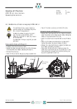
Страница 18: ... ing device provided can be used For this purpose screw the grease nipple which is parked in a dummy hole on the right motor foot view on traction sheave into the regreasing hole which is located near the rotor centre see picture below Before doing this remove the plug screw DIN 908 B M10x1 which protects the regreasing hole Use a KP2N 30 grease to DIN51502 e g Wälalit LZ2 or Klüberlub BE 41 542 T...

Страница 19: ... see Release lever set with remotely controlled bowden cable By inserting lever rods dia max 20mm the brakes can be released manually The brake lever plates and the asso ciated counter plates also have holes and slots to which Bowden cables can be attached By using special lever devices the brakes can then also be released remotely by hand within certain limits Such devices are shown in the figure...

Страница 20: ...ing sure that the nut 1 is screwed flush onto the stud bolt 2 Caution Mount Bowden cable symmetrically for round holders see pictures below Differences between 2 or 3 brakes must be considered 4 Insert the ends of the Bowden cables into the machine 2 1 5 Then insert the sleeve ends A certain amount of effort is needed as the cables require some preloading Note The Bowden cables should be kept stra...

Страница 21: ... The lift must be braked when changing the bolt A mechanical return motion device can be fitted at the operator s own responsibility if the lift needs to be moved manually in case of a breakdown or if the car is caught by a safety device The use of the return motion device is shown in the drawing Bolt the bearing block to a cross beam at the recommended spacing The cross beam is firmly connected t...

Страница 22: ...eaded forcing holes and force off the traction sheave Danger Assembly Clean the traction sheave and the rotor flange For better assembly heat up traction sheave Slide the traction onto the rotor flange as far as possible Insert the fastening bolts and tighten diagonally oppo site bolts Use omnifit 100 or a similar adhesive to secure the bolts Tighten them along the bolt hole circle MA 115Nm with a...

Страница 23: ...ilar product Tighten them with a torque spanner using a torque of MA 115Nm Remove the M6 x 65 release screws Insert the M6x40 spring bolts Release the brake electrically and adjust the brake air gap by means of the adjusting screws sB 0 5 0 1mm Make sure that the two friction linings and the brake disc are symmetrical using a feeler gauge Switch the brake on and off several times and check the air...

Страница 24: ...cing the brake Remove the screws 2 Force off the pinned 3 flange 4 using a suitable tool Note Take off the brake carefully and remove the pins Fitting the brake with flange 1 Release the brake manually with the release screws and place it carefully on the brake disc 5 When fitting the brake on top add the 4mm shim 6 Screw in loosely the 4 screws M10x25 on top M10x30 2 Remove the release screws cau...

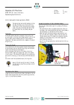
Страница 25: ...il to the switch point in direction of the microswitch C For definition of the switch point the hexagon head screw has to be turned very slowly Following the hexagon head screw B has to be scre wed additional 60 in direction of the microswitch Secure the hexagon head screw B with hexagon nut D While securing please mind that the position of the hexagon head screw may not be changed Hexagon nut and...

Страница 26: ... 0 02mm Clean the stud and the measuring system shaft end do not grease them Remove the cable cover from the measuring system Plug in the measuring system insert the M5x50 faste ning screw in the hollow shaft and tighten the screw MA 5 2Nm Turn the measuring system so that the cable can be suitably routed Tighten the clamping ring on the measuring system MA 0 65Nm Insert the cable p c b connector ...

Страница 27: ... failure of one brake the other brakes must be kept open separately even if the safety circuit is open This should preferably be done using suit able electric circuitry but can also be performed manual ly This state must not be maintained in the long term Observe the lift during this test If it does not decelerate close the open brake circuit immediately Monitoring the brakes Check the brake monit...

Страница 28: ...ation rectifier defective Check electrical connection Check braking voltage supply voltage Remove mechanical blocking Replace overexcitation rectifier Delay in braking system release Overexcitation rectifier defective Replace overexcitation rectifier Braking system does not engage Brake shoe mechanically blocked Remove mechanical blocking Delay in engaging of braking system Switch off time too sho...

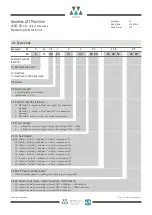
Страница 29: ...nk voltage of 500 620V 6 suitable for converter supply using a link voltage of 260 350V X3 X4 Rated speed e g 06 60min 1 with DT 400mm v 0 6m s suspension 2 1 09 95min 1 with DT 400mm v 1 0m s suspension 2 1 15 153min 1 with DT 400mm v 1 6m s suspension 2 1 19 190min 1 with DT 400mm v 2 0m s suspension 2 1 24 240min 1 with DT 400mm v 2 5m s suspension 2 1 06 67min 1 with DT 340mm v 0 6m s suspensi...

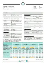
Страница 30: ...11 6 25 0 240 14 8 31 7 240 18 6 41 3 240 27 6 62 5 The table is applicable for an overall shaft efficiency of approx 72 78 counterweight 50 It lists a standard selection of machines The lift and project data will be adapted to the actual site conditions and may deviate from the above values Duty type S3 40 ED Traction sheave dia 400mm or dia 340mm Traction sheave hardnesse min 220 HB 30 Typical n...

Страница 31: ...286 16 0 47 55 45 70 66 260 296 296 17 0 52 82 72 272 308 308 18 0 57 50 90 76 280 316 316 22 0 63 45 40 124 147 404 32 0 82 340 DR 296 70 86 280 316 316 16 0 47 50 40 95 98 5 305 341 341 22 0 63 45 Motor motor WSG 08 1 08 2 08 3 08 4 F 184 220 220 220 FL 134 170 170 170 LM 260 296 296 350 Masse weight mM kg 282 310 324 397 Trägheitsmoment inertia JM kgm2 2 8 3 0 3 2 3 3 Dimensions mm Mitte Treibk...

Страница 32: ...N1313 EnDat or SSI 503 325 021 xx D Pack Arkel ADrive CT unidrive SP ECN1313 EnDat or SSI 502 452 021 xx emotron Dietz DSV 5445 ECN1313 EnDat or SSI 501 112 022 xx Fuji Frenic ECN1313 EnDat 502 679 022 xx KEB F5 ECN1313 EnDat 502 363 022 xx LTi DRiVes Lust CDD 3000 ECN1313 SSI 505 677 022 xx RST Elektronik FRC ECN1313 EnDat 508 752 022 xx GEFRAN SIEI AVY L M ERN 1387 503 599 022 xx Vacon NXP ECN13...

Страница 33: ...4 P E g n g e x x i s o l i e r t e A d e r e n d h ü l s e n 1 5 m m 2 S A D A r t N r 3 6 6 1 1 1 2 9 1 8 8 1 0 0 1 5 0 1 6 5 K a b e l f ü r T e m p e r a t u r ü b e r w a c h u n g x x i s o l i e r t e A d e r e n d h ü l s e n 0 7 5 m m 2 S A D A r t N r 3 6 6 1 1 1 2 9 1 6 3 A n s c h l u ß a u f K l e m m b r e t t A d e r 1 T F ü h l e r s c h w a r z 2 T f ü h l e r b l a u 5 0 C o n C ...

Страница 34: ...n 9 4 Emergency evacuation Änderungen vorbehalten Subject to changes without notice The remote control of the brake by Bowden cable is used to release the brakes mechanically in the case of an emergency For details of this method see section 9 4 Emergency evacuation The standard length of the Bowden cable is 3m Other lengths on request 13 3 Release lever set with remotely controlled Bowden cable R...

Страница 35: ...type code X5X6X7 02 Hydraulic type lubricating nipple DIN71412 AM 10x1 03 Dummy stopper N Pg9 DIN46320 Fs 04 Rope slip off guard cpl 505648 05 Measuring system depending on spec ECN1313 SSI 2048 incr clamping ring ECN1313 ENDAT 2048 Inkr clamping ring ERN1387 2048 Inkr clamping ring Brake system 06 Overexcitation rectifier 3217320A23 from Binder GmbH to 06 2006 BEG 561 255 130 from intorq GmbH as ...

Страница 36: ......

Страница 37: ......

Страница 38: ...r of the traction sheave from rope s center to rope s center m DBS Diameter of the brake disk effectively m vBS Gliding speed on the brake disk diameter effectively m s i Ratio of the car suspension Maximum tripping speed on the brake disk diameter effectively 8 25 m s 1 2 Use as braking element part of the protection device against unintended car movement act ing in up and down direction permissi...

Страница 39: ...e shaft itself has to be statically supported in two points The calculation evidence must be enclosed with the technical documentation of the lift 2 6 The setting of the brake force has to be secured against unauthorized adjustment e g sealing lacquer 2 7 The identification drawing no 5019001 including stamp dated 2016 03 18 shall be included to the EU type examination for the identification and i...

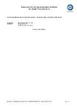
Страница 40: ...5 of 2016 03 18 Based on Application form from Co INTORQ GmbH Co KG of 2015 12 02 Page 1 of 1 Authorised Manufacturer of Serial Production Production Sites valid from 2016 03 18 Company INTORQ GmbH Co KG Address Wülmser Weg 5 31855 Aerzen Germany END OF DOCUMENT ...

Страница 41: ......

Страница 42: ...www intorq com setting the standard www intorq com INTORQ BFK466 55 Multi pole spring loaded brake Translation of the Original Operating Instructions ...

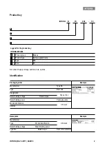
Страница 43: ...roduct type Spring applied brake Type 466 Size 55 Packaging label Example Manufacturer Type No Type Bar code Designation Qty per box Rated holding voltage Rated torque Rated holding power Packaging date Model identification CE mark Addition Nameplate Example Manufacturer CE mark Type Model identification Rated holding voltage Rated holding power Type No Rated torque Date of manufacture A A B C D ...

Страница 44: ...A 14 0177 04 2016 3 Document history Product traceability sticker Example Type QR code Type No Serial number Manufacturer Material number Version Description 13054724 1 0 04 2016 SC First edition for the series ...

Страница 45: ...d brake 10 2 4 Safety instructions and notices 10 3 Technical specifications 12 3 1 Product description 12 3 2 Rated data 14 3 3 Switching times 15 3 4 Switching energy switching frequency 16 3 5 Emissions 17 4 Mechanical installation 18 4 1 Necessary tools 18 4 2 Assembly 18 4 3 Installation 19 5 Electrical installation 20 5 1 Electrical connection 20 6 Commissioning and operation 22 6 1 Performi...

Страница 46: ... system Drive systems with spring applied brakes and other drive compo nents Letter symbol Unit Designation FR N Rated frictional force I A Current IH A Holding current at 20 C and holding voltage IL A Release current at 20 C and release voltage IN A Rated current at 20 C and rated voltage MA Nm Tightening torque of fixing screws Mdyn Nm Braking torque at a constant speed of rotation MK Nm Rated t...

Страница 47: ... air gap sLmin mm Minimum air gap sLmax mm Maximum air gap sHL mm Air gap for manual release t1 ms Engagement time sum of the delay time and braking torque rise time t1 t11 t12 t2 ms Disengagement time time from switching the stator until reaching 0 1 Mdyn t3 ms Slipping time operation time of the brake according to t11 until stand still t11 ms Delay during engagement time from switching off the s...

Страница 48: ...s immediately to your INTORQ representative 1 6 Drive systems 1 6 1 Labelling Drive systems and components are unambiguously designated by the indications on the name plate Manufacturer INTORQ GmbH Co KG Wülmser Weg 5 D 31855 Aerzen Germany 1 6 2 Application as directed Drive systems are to be used in machines and systems must only be used for the purposes ordered and confirmed must only be operat...

Страница 49: ...riptions We do not accept any liability for damage and operating interference caused by inappropriate use unauthorised modifications to the product improper working on and with the drive system operating faults disregarding these Operating Instructions Warranty Terms of warranty Refer to the terms of sale and delivery for INTORQ GmbH Co KG Please submit warranty claims to your INTORQ representativ...

Страница 50: ...ng these safety notices Please contact your local INTORQ representative if you have questions or problems The spring applied brake corresponds to the state of the art at the time of delivery and is generally safe to operate The spring applied brake is hazardous to persons the spring applied brake itself and other properties of the operator if non qualified personnel work on and with the spring app...

Страница 51: ...al connections against any contact or touching 2 4 Safety instructions and notices The following icons and signal words are used in this document to indicate dangers and important safety in formation Safety instructions Structure of safety instructions SIGNAL WORD Icon Indicates the type of danger Signal word Characterises the type and severity of danger Note Describes the danger Possible conseque...

Страница 52: ...njury WARNING WARNING indicates a potentially hazardous situation which if not avoided could result in death or serious injury CAUTION CAUTION indicates a hazardous situation which if not avoided could result in minor or mod erate injury NOTICE Notice about a harmful situation with possible consequences the product itself or surrounding objects could be damaged ...

Страница 53: ...g torque is generated by the pressure of several compression springs 8 via friction locking be tween the two friction linings 11 of the friction lining support 7 and the flange 3 and the brake disc The brake is released electromagnetically The suitable switching device rectifies the supply voltage AC voltage and decreases it after a short time when the brake is released This results in a reduction...

Страница 54: ...e friction linings ensure high braking torque and low wear 3 1 3 Brake release When the brake is being applied there is an air gap sL between the friction lining carrier 7 and the pole faces of the stator 1 To release the brake the coils of the stator 1 are supplied with DC voltage from the associated switching device The resulting magnetic force pulls the armature plate 7 to the pole faces of the...

Страница 55: ...ter Max Speed Voltage1 Power2 Coil resistance Max current MK Nm da mm nmax min 1 U V DC P20 W R20 5 Imax A BFK466 55 730 450 500 205 473 118 88 80 2 31 925 550 400 1270 750 300 Type Air gap Max air gap Fixing screws Tightening torque Max perm switching energy Transitional switching frequency Weight without brake disc sLN mm sLmax mm MA Nm QE J Shue h 1 m kg BFK466 55 0 4 0 1 1 0 2 x M12 10 9 115 2...

Страница 56: ...hing operations Engagement time For emergency braking short engagement times for the brake are absolutely essential The DC switching in connection with a suitable spark suppressor must therefore be provided If the drive system is operated with a frequency inverter so that the brake will not be de energized before the motor is at standstill AC switching is also possible not applicable to emergency ...

Страница 57: ...ching energy as a function of the switching frequency The permissible switching frequency Shzul depends on the switching energy Q At a pre set switching fre quency Sh the permissible amount of switching energy is Qzul J h 1 Switching frequency Sh Switching energy Q S hzul Shue ln 1 Q QE Qzul QE 1 e Shue Sh ...

Страница 58: ...nd possible heat dissipation Un der unfavourable conditions the surface temperature can reach 130 C Noise The loudness of the switching noise during engaging and disengaging depends on the air gap sL and the brake size It is approximately 60 to 65 db A Miscellaneous Abrasion due to emergency braking occurs in the form of dust In case of high load the friction face will become so hot that odours ma...

Страница 59: ...rake 2 Check for completeness 3 Verify the nameplate data especially the rated voltage NOTICE Do not lubricate the screws with oil or grease Type Torque wrench Insert for hexagon socket screws Transport screw Cross tip screwdriver Measurement range NM Width across flats mm Wrench width mm Cross tip size BFK466 55 250 14 x 1 2 square 6 x 1 4 square 2 Multi meter Calliper gauge Feeler gauge ...

Страница 60: ...e specified torque 14 3 Check the clearance of the brake disc 2 Check the air gap sL between the two friction linings 4 and the brake disc 2 using a feeler gauge 5 4 Remove the transport safety bolts 1 5 Switch the current on and off several times checking the movability of the brake on the guide sleeves Fig 4 Procedure for installing the BFK466 55 spring applied brake NOTICE The sum of the measur...

Страница 61: ... at the same time Fig 5 Connection diagram for the BFK466 circuit proposal for DC switching DANGER There is a risk of injury by electrical shock Perform electrical connection only when no voltage is applied If an emergency stop is carried out without the required suppressor circuit the control unit may be destroyed Observe the correct polarity of the suppressor circuit 230V AC L1 N K1 K2 Bremse 1 ...

Страница 62: ...al When current is fed to the spring applied brake the armature plate is released The microswitch NO contact is actuated and gives the signal Spring applied brake released Input connection black N O contact blue connection NC contact grey connection bl sw Mikroschalter Microswitch Brake ...

Страница 63: ...r terminals The measured level must be zero 3 Switch on the current for the brake 4 Measure the AC voltage at the motor terminals It must be the same as the mains voltage 5 Check the air gap sL between the brake disc and friction lining It must be a total of 0 4 0 1 mm The brake disc must be able to be turned freely 6 Switch off the power supply 7 Screw the bridges onto the motor terminals DANGER ...

Страница 64: ...l considerable increase in resistance is felt 2 The rotor must turn freely A low residual torque is permitted 3 Release the lever 6 2 During operation Checks must be carried out regularly during operations Pay special attention to unusual noises or temperatures loose fixing attachment elements the condition of the electrical cables If a fault or malfunction occurs look through the error search tab...

Страница 65: ...and friction lining It should not ex ceed SLmax according to the table 14 3 Switch off the power supply 7 3 Maintenance The brake does not require any maintenance when it is being used as a holding brake The brake is replaced in the reverse order of the assembly 18 1 Switch on the current for the brake or screw in the transport screws M6x65 with Ø23 washer 2 Loosen the fixing screws at the guide s...

Страница 66: ... BFK466 55 spring applied brake Electrical accessories Order quantity Pieces Size 55 Voltage 103 V 205 V Cable length Standard mm from 100 1000 mm in 100 mm steps from 1000 2500 mm in 250 mm steps Terminal box installed Manual release installed PTC sensor Rectifier with overexcitation ...

Страница 67: ...tage refer to section on defective rectifier voltage too low Wiring defective or wrong Check the wiring and correct Check the cable for continuity using a multimeter Replace defective cable Rectifier defective or incorrect Measure rectifier DC voltage using a multimeter If DC voltage is zero Check AC rectifier voltage If AC voltage is zero Switch on power supply Check fuse Check wiring If AC volta...

Страница 68: ...ring Check and correct the wiring of the microswitch Microswitch defective or incorrectly set Replace the brake and send the defective brake to the manufacturer Voltage too high Brake voltage does not match the rectifier Adjust rectifier and brake voltage to each other Voltage too low Brake voltage does not match the rectifier Adjust rectifier and brake voltage to each other Defective rectifier di...

Страница 69: ...Notes INTORQ BA 14 0177 04 2016 28 Notes ...

Страница 70: ...i Co Ltd р ᐸ ђ ค䭽 ݹ 䐥 ਭ ਭᾲжᾲ ᓝ No 600 Xin Yuan Nan Road Building No 6 Zone B Nicheng town Pudong 201306 Shanghai China 86 21 20363 810 86 21 20363 805 info cn intorq com INTORQ US Inc USA 300 Lake Ridge Drive SE Smyrna GA 30082 USA 1 678 236 0555 1 678 309 1157 info us intorq com INTORQ India Private Limited India Plot No E 7 3 Chakan Industrial Area Phase 3 Nighoje Taluka Khed Pune 410501 Maharas...

Отзывы: