English _
11
!
PTZ CAMERA (QNP-6320/QNP-6250)
`
Camera Wiring Interface Board
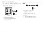
For the camera wiring, please refer to the picture below.
Refer to Control Signal Connection Diagram
PoE+
Audio
IN
Audio
OUT
Alarm
Alarm Input
Alarm output
J
`
Select Normal Open in the setup menu.
-
The sensor input is activated during a short for contact type, or when it is at “Low” level for the active type.
`
Select Normal Close from the Setup menu.
-
The sensor input is activated when open for the contact type or when in high impedance state (open collector) for the
active type.
`
The maximum capacity of the alarm output terminal is 30V DC/2A, 125V AC/0.5A and 250V AC/0.25A.
`
When connecting alarm input and output cables, be sure to connect one cable to each terminal respectively.
`
To connect products over the camera’s capacity, please use an additional relay device.
`
If power and GND cables are connected inappropriately to the NC/NO or COM port, a fire or breakdown of equipment may
occur.
`
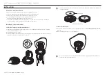
Connecting Camera Safety Cable and Attaching Camera
1.
First, as shown in the left hand picture, pull out the safety cable from the base and then hook it to the
mount. The safety cable is coiled inside the base.
`
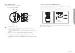
To attach the camera to the mount, refer to the alignment guide marks as shown in the picture.
2.
Carefully attach the camera to the mount following the alignment guide marks as shown in the picture.
J
`
Make sure to hook the camera’s safety cable to the mount before proceeding. Otherwise you may be exposed to serious
injury caused by the camera falling.
Align the
Direction Guides
Direction
Guides
Direction
Guides
Содержание QNP-6250
Страница 1: ...NETWORK CAMERA User Manual QNP 6320H QNP 6320 QNP 6250H QNP 6250 ...
Страница 7: ...English _7 OVERVIEW QNP 6320 QNP 6250 QNP 6320H QNP 6250H 8 14 ...
Страница 35: ......


