English _
9
●
●
OVER
VIEW
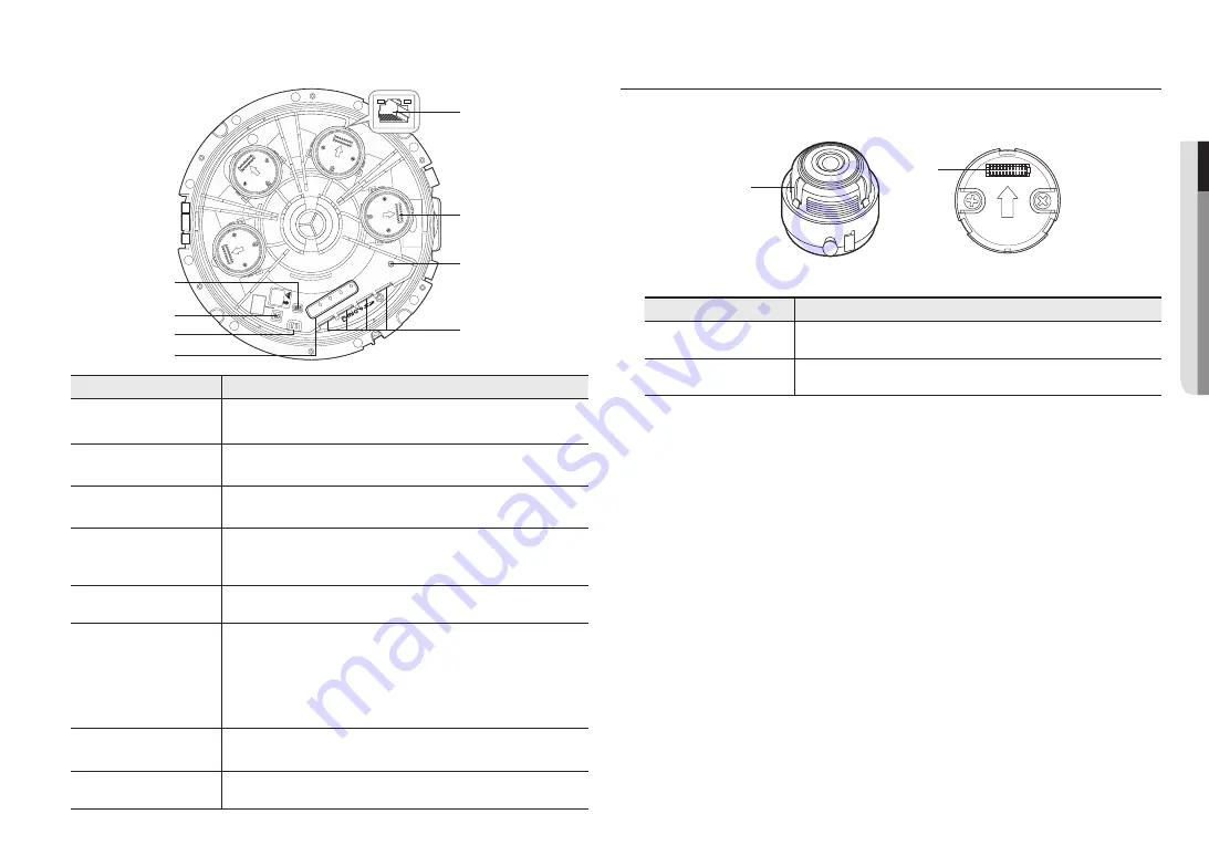
Components
Item
Description
a
Power On/Off switch
Switch used to turn the product On/off.
J
Use it only to replace your lens module.
b
Channel DIP Switch
Change the DIP switches to specify the channel you want to use to view the installation
video.
c
Test Monitor Out Port
Output port for test monitoring the video output. Use the test monitor cable to connect to a
mobile display and check the test video.
d
Status Indicators for Lens
Module (normal: green,
abnormal: red)
If the lens module is attached correctly, the green LED will illuminate and then turn off after
approximately 40 seconds. (to prevent undesirable reflections)
e
Micro SD Card slot
Compartment for the Micro SD card.
f
Reset Button
The button restores all camera settings to the factory default.
Press and hold for about 5 seconds to reboot the system.
J
If you reset the camera, the network settings will be adjusted so that DHCP can be
enabled. If there is no DHCP server in the network, you must run the Device Manager
program to change the basic network settings such as IP address, Subnet mask,
Gateway, etc., before you can connect to the network.
g
Lens module mounting
portion
This is the terminal to mount the lens module.
h
PoE+ port
The terminal connects power and network through the PoE+ cable.
1
1
1
0
0
2
ON
RESET
1
2
3
4
CH 4
CH 3
CH 2
CH 1
ON / OFF
Ple
ase
turn off whenyou chang
e
lens module.
LENS
1
VIDEO
CH
00 : CH 1
10 : CH 2
01 : CH 3
11 : CH 4
2
3
4
f
e
g
b
c
d
a
h
AT A GLANCE (LENS MODULE)
Appearance
Item
Description
a
Lens module
This is a lens module that records video.
b
Camera connector
This is a terminal to connect with the camera.
a
b


