SmartPAC 2 User Manual
1126700
Installation
2-27
Example
Say you wish to use three standard relays and one solid state relay. You would install the three
standard relays in channels 1 through 3, and the solid state relay in channel 5, skipping the
channel 4 output for all wiring and programming.
4.
To remove a relay, pull the plastic retention clip away from the relay and pull the relay
straight out of its socket. When re-inserting the relay, make sure that the pins line up with
the socket holes, then press in firmly.
5.
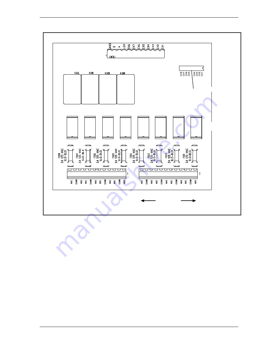
Locate the 12-conductor cable(s) for wiring the ProCamPAC board (see Figure 2-13,
page 2-20 for layouts of 8- and 16-channel boards) to terminal block TB301 inside the
ProCamPAC Output enclosure. If you are wiring an 8-channel ProCamPAC, one cable is
supplied (for channels 1-8). If you are wiring a 16-channel board, two cables are supplied,
one for channels 1 through 8, the other for channels 9 through 16.
Figure 2-15. Cam Outputs Board
Cam 4
Solid State Relays
Channels 5-8
LEDs for channels
Connection to
press control
Relay 1
K301
Relay 2
K302
Relay 3
K303
Relay 4
K304
Relay 5
K305
Relay 6
K307
K309
K311
Use only one relay
(mechanical or solid state)
for each channel
Mechanical
Relays
TB303
TB302
CHAN 1
CHAN 2
CHAN 3
CHAN 4
CHAN 5
CHAN 6
CHAN 7
CHAN 8
Fuses
DS301
TB301
Connect to loads
to be controlled
Cam 1
Cam 3
Cam 2
Counter
on - 200
off - 250
o
o
Содержание SmartPAC2
Страница 21: ...1126700 SmartPAC 2 User Manual xviii Table of Contents ...
Страница 143: ...1126700 SmartPAC 2 User Manual 4 46 Initialization Mode ...
Страница 197: ...1126700 SmartPAC 2 User Manual 5 54 Program Mode ...
Страница 233: ...1126700 SmartPAC 2 User Manual 6 36 Run Mode ...
Страница 245: ...1126700 SmartPAC 2 User Manual 7 12 Fault Messages ...
Страница 271: ...1126700 SmartPAC 2 User Manual B 12 Updating SmartPAC 2 Firmware ...
Страница 309: ...1126700 SmartPAC 2 User Manual E 6 Replacing SmartPAC 2 PC Board ...
Страница 379: ......
Страница 380: ......
Страница 381: ......
Страница 382: ......
Страница 383: ......


