2
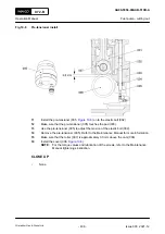
Release the pressure of the servo oil supply unit to 0 bar.
3
) from the defective fuel pump (003). Refer to
the Maintenance Manual for more information.
4
Install the flange (002) to the fuel pump (003).
5
Install the flange (007) to the intermediate piece (006).
6
Remove the applicable cover (005) from the supply unit casing (004).
NOTE:
Make sure that the applicable supply unit cam is at TDC and if not do
.
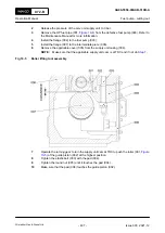
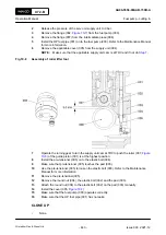
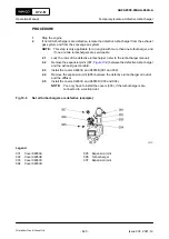
Fig 10-5
Roller lifting tool assembly
7
Operate the turning gear to turn the supply unit cam at TDC to push the roller (001,
) of the guide piston (002) at the highest position.
8
Tighten the elastic bolt (003) with the pad (004).
9
Tighten the round nut (005) until it touches the pad (004).
10
Make sure that the pad (004) touches the guide piston (002).
X72-B
AA00-5556-00AAB-510B-A
Operation Manual
Fuel pump - cutting out
Winterthur Gas & Diesel Ltd.
- 437 -
Issue 003 2021-12
Содержание X72-B
Страница 8: ...X72 B Operation Manual Page left intentionally blank Winterthur Gas Diesel Ltd 8 Issue 003 2021 12...
Страница 18: ...X72 B Operation Manual Page left intentionally blank Winterthur Gas Diesel Ltd 18 Issue 003 2021 12...
Страница 137: ...X72 B Operation Manual Page left intentionally blank Winterthur Gas Diesel Ltd 137 Issue 003 2021 12...
Страница 301: ...7 Installation 7 1 Installation 302 X72 B Operation Manual Winterthur Gas Diesel Ltd 301 Issue 003 2021 12...


