User’s Manual
Custom Embedded Solutions
WIN Enterprises, Inc.
[email protected]
www.win-ent.com
(978) 688-2000
1
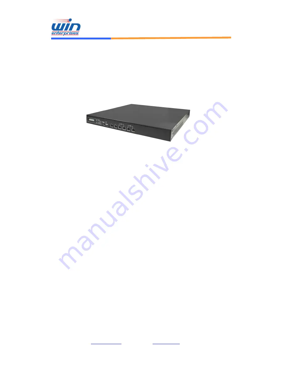
PL-80470
Networking Appliance
1U Rack-Mount Intel® Sandy/Ivy Bridge Core i7/i5/i3
Network System, 6 Copper GbE, SATA, CF, LCM, PCI-E,
Bypass
User’s Manual
Version 1.0a, 212


