background image

I

n s t a l l a t I o n


a n d

  C

a r e

  G

u I d e

Содержание Subsonic

Страница 1: ...In s t a l l a t i o n a n d C a r e G u i d e ...

Страница 2: ...ng an d th e M arketin g D epar t m ent The informat io n conta ined herein is subjec t to change w ith ou t n o tice Cu r rent Revis io n 1 0 If yo u are in need of a more recent manual please cont ac t yo ur d eal er o r downlo ad o ne at w w w wilsonaudio com The i nfo rm atio n in t h is manua l is the sole proper t y of Wil son Au d io S p ecial t ies I n c Any reprod uc ti o n in whole or in...

Страница 3: ... i o n 2 2 Co n n e c t i n g t h e C o n t r o l l e r 1 3 C o n n e c t t h e C o n t r o l l e r t o t h e Wi l s o n A u d i o S u b s o n ic A mp l i f i e r 1 3 B y p a s s i n g t h e H ig h P a s s F i l t e r 1 4 Ut i l i z i n g t h e H ig h P a s s F i l t e r 1 5 S e c t i o n 3 C o n t r o l l e r F i n a l S e t u p 1 9 S e c t i o n 3 1 F r o n t P a n e l S e t u p a n d F i n a l ...

Страница 4: ... o l t Tr igg e r C o n t r o l s 3 2 S e c t i o n 4 F i n i s h i n g U p 3 7 S e c t i o n 4 1 S pi k e In s t a l l a t i o n H o r i z o n t a l 3 8 P l i n t h a n d S pi k e In s t a l l a t i o n 3 9 A s s e m b l y a n d C a r e o f t h e G r i l l s 40 S e c t i o n 4 2 S pi k e In s t a l l a t i o n V e r t ic a l 40 S pi k e A s s e m b l y 40 S e c t i o n 4 3 Us i n g t h e Li f t t...

Страница 5: ... 51 S e c t i o n 5 3 S p e ci f ic a t i o n s C o n t r o l l e r 52 S e c t i o n 5 4 Gr a p h ic a l D im e n s i o n s C o n t r o l l e r 53 S e c t i o n 6 W a r r a n t y 5 5 S e c t i o n 6 1 Limi t e d Wa r r a n t y 56 S e c t i o n 6 2 Co n d i t i o n s 56 S e c t i o n 6 3 Re m e d y 57 S e c t i o n 6 4 Wa r r a n t y Limi t e d t o O r igi n a l P u r c h a s e r 58 S e c t i o n 6...

Страница 6: ......

Страница 7: ...S e c t i o n 1 U n c r a t i n g W i l s o n A u d i o S p e c i a l t i e s ...

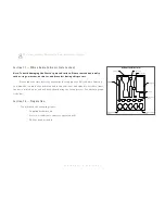
Страница 8: ...Audio Subsonic to review the contents of your Wilson Audio Subsonic tool and spike kit Set these items in an accessible area as you will need them during the setup process See the two graph ics below Section 1 2 Preparation You will need the following items Supplied hardware kit Electric screwdriver or battery operated drill Phillips head drive bit Caster Wrench 1 2 Nut Driver 1 4 Allen Elbow Poli...

Страница 9: ...n Audio Subsonic will not roll out of the crate with this packing material in place 2 Carefully rotate the crate so that the Wilson Audio Subsonic is upright 3 While one person holds the crate the other two helpers should gently roll the Wilson Audio Subsonic out of the crate Be care ful not to scratch the sides of the painted enclosure 4 Move the Wilson Audio Subsonic into the desired location It...

Страница 10: ......

Страница 11: ...S e c t i o n 2 I n i t i a l S e t u p W i l s o n A u d i o S p e c i a l t i e s ...

Страница 12: ...s are positioned on the side that best accommodates cable installation Because the Wilson Audio Subsonic s frequency range is limited to the sub frequency bass range its placement requirements are fundamentally dif ferent than for a full frequency speaker The Wilson Audio Subsonic reproduce a relatively small percentage of the audio spectrum with a typical bandwidth of less than two octaves The st...

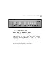
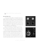
Страница 13: ... outputs contain identical signals There is a single ended and a balanced connector for each output If you are using one subwoofer connect the amplifier driving the subwoofer to the Controller s LOW PASS OUT via the 1 output Choose either the balanced cable or single ended output to match the input configuration of the amplifier If you are using two subwoofers with separate amplifiers connect the ...

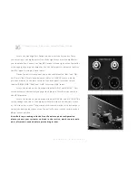
Страница 14: ...bwoofer without the use of the High Pass filter Make sure the Controller power is off during the connecting process Locate the input section of the Controller on the rear of the unit Controller inputs are configured for both balanced XLR and single ended RCA cables When connecting the Controller without the use of the High Pass Filter a second output from your preamplifier is required If your prea...

Страница 15: ... LP OUT Select LP IN Proceed to Section 3 1 Front Panel Setup and Final Tuning to continue the setup of your unit Utilizing the High Pass Filter The Controller employs a high quality High Pass Filter as a part of its crossover design The High Pass Filter can be used to filter bass from the main loudspeakers This can be desirable in systems where the main loudspeakers have limited bass dynamics or ...

Страница 16: ...switch labeled PROCESSOR REM and LINE Select the LINE input Locate the switch on the front panel labeled HP IN and HP OUT This switch defeats or alternatively engages the high pass filter Turn the switch to the HP IN position Locate the switch on the front panel labeled HP 6 dB and HP 12 dB This switch changes the slope of the high pass filter to either 6 decibels per octave or 12 decibels per oct...

Страница 17: ...Se c t ion 2 2 Con n e c t i ng t h e Con t rol l e r 17 W i l s o n A u d i o S p e c i a l t i e s ...

Страница 18: ......

Страница 19: ...S e c t i o n 3 C o n t r o l l e r F i n a l S e t u p W i l s o n A u d i o S p e c i a l t i e s ...

Страница 20: ...closely to ensure the best possible result from your Controller You will need the following items Supplied WATCH Dog Controller Setup CD dB Meter Pen and paper to make notes Double check the switch control settings to ensure that they are in the proper positions as outlined in Section 2 In this section you will be adjusting and fine tuning the Controller front panel Locate the main power switch on...

Страница 21: ...cisely to the use of the Controller in conjunction with a subwoofer in a two channel mu sic system However these procedures can also be used to optimize the Control ler to the left and the right channels of a multi channel home theater system Wilson Audio Subsonic Placement The Controller possesses sophisticated low pass filter control features as well as the ability to continuously vary phase ang...

Страница 22: ...cally true what is more important is the complex low frequency room interaction that will occur between the subwoofer s output and the full range output of the L and R channels This LF interaction is greatly re duced if LF to the L R speakers is filtered out For the greatest finesse in music reproduction you should experiment with both approaches Initial Placement of the L R Speakers If both the s...

Страница 23: ...pressure lev el SPL meter you should measure and document the in room response of your L R loudspeakers running full range with out subwoofer contribution This will give you a baseline mea surement While you can measure each channel individually it is more expedient to measure both simultaneously using the Mono test signals Measurement locations for the microphone should include one at ear height ...

Страница 24: ...off in the bass If your mea surements follow the profiled roll off it indicates a very linear speaker room response Use track 2 pink noise for spectrum analysis measurements For measurements using a SPL meter use tracks 6 through 16 1 3 octave BLN beginning at 200 Hz and going down to 20 Hz Document your measured results Warning Tracks 17 through 27 are sine wave tones at the 1 3 octave center fre...

Страница 25: ...ly analogous manner Using the High Pass Filter If you choose to use the high pass section of the Controller to roll off bass to your main speakers you can use your measured data to select a low pass LP frequency The suggested setting for the high pass frequency is at the point where the measured frequency curve begins to roll off specifically at the frequency that is minus three to minus six dB re...

Страница 26: ...o might include problematic room acoustics with a significant upper bass peak In such a case correction may be achieved by running the Controller up to 120 140 Hz and using its EQ to notch out the room peak This is one area where acoustical measurements as described above are of great benefit The Controller into Your System 4 Check to see that the L R loudspeaker power amps are Off or on Standby 5...

Страница 27: ...trol at 90 10 Select EQ Out at this point in the calibration 11 The output level control should be in the Min position 12 Turn on the program source components and pre amplifiction 13 After two minutes of stabilization time turn on your Controller 14 After two additional minutes of stabilization time turn on your L R channel power amplifiers 15 Using track 2 pink noise turn the L R speakers up to ...

Страница 28: ...put is greatest These two settings become your semifinalists 20 Go to track 28 drum and guitar music and compare the sound of your two Phase semifinalists Listen for cleaner LF attack and greater weight to select your winner Note the winning setting 21 Use two tracks 29 and 32 to establish the WATCH Controller s upper frequency limit with the LP frequency control setting What you are looking for i...

Страница 29: ...e ments You should now clearly observe more output below 40 Hz as well as good linearity 24 Now is a good time to experiment with different filter slopes Simply follow the same procedures as above being careful to note all settings This second experiment can then be com pared with the first using music and measurements Pick the approach that gives the most satisfying musical results To EQ Or To No...

Страница 30: ... of the subwoof er is more likely to excite modes than a placement at least one meter from a corner A significant narrow dip in LF response caused by acoustical losses in the room These bass dips can be caused by tall ceil ings openings such as windows and doors particularly near corners or at the middle of a long wall or a small non load bearing wall which acts as a panel resonator bass trap Thes...

Страница 31: ...perfect flatness of response is misguided Possibly this is because the test signal i e pink noise causes a relatively continuous excitation of reso nances This allows the amplitude to build up appearing in measurements as a large deviation from optimum A great deal of music because of its more tran sient nature may not cause these non linearities to build up as much Hence the tendency to over corr...

Страница 32: ...tely fifty hours of play time Section 3 4 Twelve volt Trigger Controls Certain features of the WATCH Controller are controllable via a series of twelve volt triggers This allows remote control access of these features by out side control systems Audio Video Controllers etc This provides more conve nient and seamless operation of the WATCH Controller within home theaters and complex audio systems T...

Страница 33: ...ed on the front control panel If you wish to control any of these features via the twelve volt trigger move the corresponding switch to the center position labeled Rem The switch for the Stand By On Off control is located on the right hand side of the front panel Leave this switch undepressed when controlling this function via the twelve volt trigger Please Note Only the switches relevant to the f...

Страница 34: ... relay switches to configure your crossover ideally for those corresponding modes Similarly control systems such as Crestron AMX and others have the option for interfacing with controllable devices via twelve volt relay triggers Consult your audio specialist or installer for more details The twelve volt triggers are two state switches the presence of zero volts no voltage on the input of the trigg...

Страница 35: ...Se c t ion 3 4 Tw e lv e volt Tr igg e r Con t rol s 35 W i l s o n A u d i o S p e c i a l t i e s ...

Страница 36: ......

Страница 37: ...S e c t i o n 4 F i n i s h i n g U p W i l s o n A u d i o S p e c i a l t i e s ...

Страница 38: ...on as well as optimal height placement for your Wilson Audio Subsonic Brass disks that fit beneath the spikes are included for installations where spikes might damage the floor surface such as wood floors Note Wilson Audio Subsonic weighs over five hundred pounds 226 80 Kg Two strong indi viduals are required to safely install spikes After determining the Wilson Audio Subsonic s position assemble ...

Страница 39: ... Wilson Audio Subsonic is placed on its side This plinth features a special padded surface on its upper that provides a degree of protec tion for Wilson Audio Subsonic s painted surface Determine the final position of Wilson Audio Subsonic Make sure to position the Wilson Audio Subsonic such that the binding posts are orient ed to the side most convenient to connection Place the plinth in this loc...

Страница 40: ...lson Audio Subsonic up enough that you are able to rotate the subwoofer onto its plinth The second person should then rotate his side onto the plinth Ensure the Wilson Audio Subsonic is centered on the plinth Remove the casters Assembly and Care of the Grills The Wilson Audio Subsonic s grilles are attached using Wilson s unique austenitic stainless pin system Each of the three grilles contain fou...

Страница 41: ...o unscrew them when you level the Wilson Audio Subsonic Place the set screw into the other end of the diode with the Allen head toward the spike This will ensure that if for any rea son you have to remove your Wilson Audio Subsonic spikes you will be able to withdraw the set screw safely using the supplied Allen wrench Screw the set screw into the diode until it meets the spike Place the assemblie...

Страница 42: ...lace the lift plate so it is positioned about an inch behind the front facade of the Wilson Audio Subsonic woofer enclosure Note An assistant should stand to the rear of the Wilson Audio Subsonic to steady it 2 Attach the wrench to the lift bolt and begin to slowly raise the front of the Wilson Audio Subsonic by turning the bolt clock wise 3 After the front of the Wilson Audio Subsonic is high eno...

Страница 43: ... Subsonic will now sit lower in the front as the spike assembly is shorter than the caster Use caution Note It is very important at this point that an able assistant stabilize the front of the Wilson Audio Subsonic until the rear spikes are attached and the unit is lowered The Subsonic is slightly front heavy so extra caution should be taken when installing the rear spikes 6 Repeat the previous pr...

Страница 44: ... To find out which spike to lower grasp the Wilson Audio Sub sonic channel and rock it back and forth This will identify the spike that is out of level from the other three Place a level on the front to back oriented axis If it is level then your Wilson Audio Subsonic s are level Using the same process as above adjust the front or rear spikes to achieve front to back level Section 4 4 Removing the...

Страница 45: ... downward and outward Note Tearing the film aggressively can damage the paint 3 Take care in removing the protective film near edges and cor ners to prevent paint damage in these areas 4 The protective film should not be left on the painted surface for extended periods of time nor exposed to heat sources and direct sunlight Wilson Audio Subsonic Grills The Wilson Audio Subsonic s grilles three tot...

Страница 46: ... gently seat the grille until it stops at the end of the receptacle If you choose to use your Wilson Audio Subsonic without grills Wilson provides grommets that insert into the receptacles to cover the grill holes These are located in the toolkit Simply press the grommets into the empty grill holes ...

Страница 47: ...Se c t ion 4 4 Re mov i ng t h e Pro t e c t i v e Fi l m 47 W i l s o n A u d i o S p e c i a l t i e s ...

Страница 48: ......

Страница 49: ...S e c t i o n 5 S p e ci f ic a t i o n s W i l s o n A u d i o S p e c i a l t i e s ...

Страница 50: ... Specifications Wilson Audio Subsonic Enclosure Type Woofer Nominal Impedance Sensitivity Overall Dimensions Weight Front Ported 3 each 12 inch dual spider 4 ohms 87 dB 1 watt 2 83v at one meter Height 65 1 16 165 25 cm with spike Depth 27 3 16 69 09 cm Width 18 1 16 45 87 cm 612 lbs 277 60 Kg ...

Страница 51: ...Se c t ion 5 2 Gr a p h ica l Dim e n s ion s Wi l s on Au dio Su b s on ic 51 W i l s o n A u d i o S p e c i a l t i e s Section 5 2 Graphical Dimensions Wilson Audio Subsonic ...

Страница 52: ...anced and single ended 2 stereo Low pass balanced and single ended 2 mono Level Frequency 30 to 150 Hz Adjustable 12 dB or 18 dB Octave Level Frequency 30 to 150 Hz Adjustable 6 dB or 12 dB Octave 0 180 degrees continuously variable Variable Frequency 30 to 150 Hz Level 10 dB and Q 2 to 2 Width 19 482mm Height 4 1 2 144mm Includes feet Depth 11 1 2 292mm Includes knobs Net 16 75 lbs 7 6 kg Approx ...

Страница 53: ...Se c t ion 5 4 Gr a p h ica l Dim e n s ion s Con t rol l e r 53 W i l s o n A u d i o S p e c i a l t i e s Section 5 4 Graphical Dimensions Controller ...

Страница 54: ......

Страница 55: ...S e c t i o n 6 W a r r a n t y W i l s o n A u d i o S p e c i a l t i e s ...

Страница 56: ...e customer must have returned the Warranty Registration Form to Wilson Audio Alternatively the warranty may be filled out on line Requirement No 2 The product must have been professionally installed by the Wilson Audio dealer that sold the product to the customer FAILURE TO COMPLY WITH EITHER REQUIREMENT NO 1 OR REQUIREMENT NO 2 WILL RESULT IN THE WARRANTY PERIOD BEING LIMITED TO A PERIOD OF 90 DA...

Страница 57: ...ation Purchaser must pay for ship ping to Wilson Audio and Wilson Audio will pay for shipping of its choice to return the product to purchaser A RETURNED PRODUCT MUST BE ACCOMPANIED BY A WRITTEN DESCRIPTION OF THE DEFECT Wilson Audio reserves the right to modify the design of any product without obligation to purchasers of previously manufactured products and to change the prices or specifications...

Страница 58: ...efit of the original purchaser of the covered product and shall not be transferred to a subsequent purchaser of the product unless the product is purchased by the subsequent purchaser from an authorized Wilson Audio Dealer who has certified the product in accordance with Wilson Audio standards and requirements and the certification has been accepted by Wilson Audio in which event the Limited Warra...

Страница 59: ...t had originally been bought for immediate resale to the retail customer Wilson Audio products are warranted for a period of 90 days unless extended to 5 years as provided above by return and filing of completed Warranty Registra tion at Wilson Audio within 30 days after product delivery to customer and the product was professionally installed by the Wilson Audio Dealer that sold the product to th...

Страница 60: ... c e l l e n c e or an exclusion or limitation of incidental or consequential damages so the above limitations or exclusions may not apply to you This Limited Warran ty gives you specific legal rights and you may also have other rights which vary from state to state ...

Отзывы: