


WILDEN PUMP & ENGINEERING, LLC
2
WIL-12310-E-04
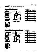
S e c t i o n 2
W I L D E N P U M P D E S I G N A T I O N S Y S T E M
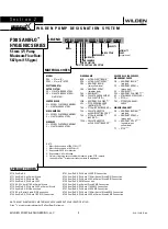
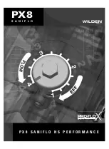
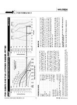
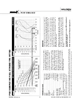
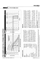
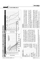
PX8 SANIFLO
™
HYGIENIC SERIES
51 mm (2") Pump
Maximum Flow Rate:
587 lpm (155 gpm)
LEGEND
PX8 / XXXXX / XXX / XX / XX /
XXXX
GASKETS
MODEL
VALVE OPTION
DIAPHRAGMS
AIR VALVE
AIR CHAMBER
CENTER SECTION
WETTED PARTS & OUTER PISTON
SPECIALTY
CODE
(if applicable)
SPECIALTY CODES
MATERIAL CODES
MODEL
PX8 = 51 mm (2")
XPX8 = 51 mm (2") ATEX
WETTED PARTS/
OUTER PISTON
SS = 316L STAINLESS STEEL
SZ = 316L STAINLESS STEEL/
NO
PISTON
CENTER BLOCK
N = NICKEL PLATED ALUMINUM
S = 316 STAINLESS STEEL
AIR CHAMBERS
N = NICKEL PLATED ALUMINUM
S = 316 STAINLESS STEEL
AIR VALVE
N = NICKEL PLATED ALUMINUM
S = 316 STAINLESS STEEL
DIAPHRAGMS
BNU = ULTRA-FLEX™ BUNA
1,5
EPU = ULTRA-FLEX™
EPDM
1,5
FBS = SANITARY BUNA
1
(two yellow dots)
FES = SANITARY EPDM
1
(two blue dots)
FSS = SANIFLEX™
1
FWL = FULL STROKE SANITARY
WIL-FLEX™
IPD
1,3,4
FWS = SANITARY WIL-FLEX™
1
LEL = PTFE-EPDM
BACKED
LAMINATE
IPD
1,2,3,4,5
TEU = PTFE w/EPDM BACKUP
1,2,5
TSS = FULL STROKE PTFE
w/SANIFLEX™ BACK-UP
1,2
TSU = PTFE
w/SANIFLEX™
BACK-UP
1,2,5
TWS = FULL STROKE PTFE
w/WIL-FLEX™ BACK-UP
1,2
VALVE BALLS, FLAP VALVES,
MUSHROOM CHECK
FB = SANITARY
BUNA
1,3,4
(red
dot)
FE = SANITARY
EPDM
1,3,4
(green
dot)
FS = SANIFLEX™
1,3,4
FW = SANITARY WIL-FLEX™
1,3,4
SF = STAINLESS STEEL FLAP
1,5
TF = PTFE
1,2,3,4
TM = PTFE MUSHROOM
CHECK
1,2
MANIFOLD GASKET
FB = SANITARY
BUNA-N
1,3,4
(red
dot)
FE = SANITARY
EPDM
1,3,4
(green
dot)
FV = SANITARY
VITON
®
1, 3, 4
(one
white/one
yellow
dots)
TF = PTFE
1,2,3,4,5
NOTE: MOST ELASTOMERIC MATERIALS USE COLORED DOTS FOR IDENTIFICATION.
Viton
®
is a registered trademark of DuPont Dow Elastomers.
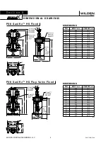
0770 SaniFlo HS
0771 SaniFlo HS, w/Swivel Stand
0772 SaniFlo HS, Wil-Gard 110V
0773 SaniFlo HS, Wil-Gard 220V
0774 HS, Wil-Gard 110V, w/Swivel Stand
0775 SaniFlo HS, Wil-Gard 220V, w/Swivel Stand
0778 SaniFlo HS, DIN Connection
0779 HS, w/Swivel Stand DIN Connection
0780 SaniFlo HS, Wil-Gard 110V DIN Connection
0781 SaniFlo HS, Wil-Gard 220V DIN Connection
0782 SaniFlo HS, Wil-Gard 110V, w/Swivel Stand DIN Connection
0783 SaniFlo HS, Wil-Gard 220V, w/Swivel Stand DIN Connection
0784 SaniFlo HS, SMS Connection
0785 SaniFlo HS, w/Swivel Stand SMS Connection
0786 SaniFlo HS, Wil-Gard 110V SMS Connection
0787 SaniFlo HS, Wil-Gard 220V SMS Connection
0788 SaniFlo HS, Wil-Gard 110V, w/Swivel Stand SMS Connection
0789 SaniFlo HS, Wil-Gard 220V, w/Swivel Stand SMS Connection
NOTE:
1. Meets Requirements of FDA CFR21.177
2. Meets Requirements of USPClass VI
3. Required for EHEDG Certification
4. Required for 3-A Certification
5. Stainless flap valve not available with reduced stroke PTFE, reduced
stroke Ultra-Flex
TM
or reduced stroke Laminate IP diaphragms
Содержание PX4 series
Страница 9: ...PX8 P X 8 S A N I F L O H S P E R F O R M A N C E S A N I F L O...
Страница 22: ...N O T E S...
Страница 41: ......
Страница 42: ...N O T E S WILDEN PUMP ENGINEERING LLC 40 WIL 12310 E 04...