


P E R F O R M A N C E
PX8 HS
Performance
17
WILDEN PUMP & ENGINEERING, LLC
SET
TING 4 PERFORMANCE CUR
VE
EMS CUR
VE
PX8 S
ANIFL
O HS REDU
CED S
TROKE PTFE SIPD-FITTED
(Sanitary Integrate Piston Diaphragm)
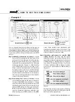
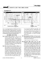
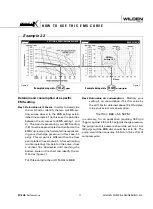
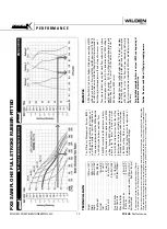
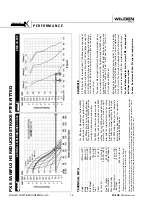
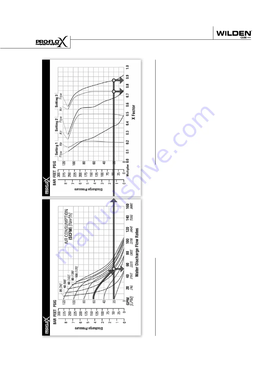
EXAMPLE
A PX8 Sanifl
o HS, reduced stroke PTFE SIPD-fi
tted pump operating
at EMS setting 4, achieved a fl
ow rate of 197 lpm (52 gpm) using 93
Nm3/h (55 scfm) of air when run at 4.1 bar (60 psig) air inlet pressure
and 1.4 bar (20 psig) discharge pressure (See dot on performance
curve).
The end user did not require that much fl
ow and wanted to reduce
air consumption at his facility
. He determined that EMS setting 3
would meet his needs. At 1.4 bar (20 psig) discharge pressure and
EMS setting 3, the fl
ow “X factor” is 0.87 and the air “X factor” is
0.74 (see dots on EMS curve).
Multiplying the original setting 4 values by the “X factors” provides the
setting 3 fl
ow rate of 171 lpm (45 gpm) and an air consumption of 69
Nm3/h (41 scfm). The fl
ow rate was reduced by 13% while the air con-
sumption was reduced by 26%, thus providing increased effi
ciency
.
For a detailed example for how to set your EMS, see beginning of
performance curve section.
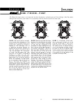
Caution: Do not exceed 8.6 bar (125 psig) air supply pressure.
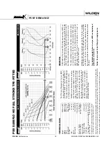
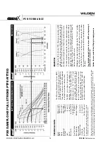
The Effi
ciency Management System (EMS)
can be used to optimize the performance of
your Wilden pump for specifi
c applications.
The pump is delivered with the EMS adjusted
to setting 4, which allows maximum fl
ow
.
The EMS curve allows the pump user to
determine fl
ow and air consumption at
each EMS setting. For any EMS setting and
discharge pressure, the “X factor” is used
as a multiplier with the original values from
the setting 4 performance curve to calculate
the actual fl
ow and air consumption values
for that specifi
c EMS setting. Note: you can
interpolate between the setting curves for
operation at intermediate EMS settings.
TECHNIC
AL D
A
T
A
Height
. . . . . . . . . . . . . . . . . . . . . . . . .
1008 mm (39.7”)
Width
. . . . . . . . . . . . . . . . . . . . . . . . . . .
460 mm (18.1”)
Depth
. . . . . . . . . . . . . . . . . . . . . . . . . . .
498 mm (19.6”)
Ship W
eight
. . . . . . . . . . . . . . . . . . . . .
49 kg (109 lbs.)
Air Inlet
. . . . . . . . . . . . . . . . . . . . . . . . . . .
19 mm (3/4”)
Inlet . . . . . . . . . . . . . . . . . . . . . . . . . . . . . . . .
51 mm (2”)
Outlet
. . . . . . . . . . . . . . . . . . . . . . . . . . . . . . .
51 mm (2”)
Suction Lift
. . . . . . . . . . . . . . . . . . . . . .
2.3 m Dry (7.4’)
. . . . . . . . . . . . . . . . . . . . . . . . . . . . . . .
9.0 m W
et (29.5’)
Disp. Per Stroke
. . . . . . . . . . . . . . . . . .
0.4 l (0.11 gal.)
1
Max. Flow Rate
. . . . . . . . . . . . . . . .
405 lpm (107 gpm)
Max. Size Solids
. . . . . . . . . . . . . . . . . . . . . . . . . . . . . .
Mushroom V
alve
. . . . . . . . . . . . . . . . .
6.4 mm (1/4”)
Ball V
alve
. . . . . . . . . . . . . . . . . . . . . . .
12.7 mm (1/2”)
Surface Finish
. . . . . . . . . . . . . . . .
Ra 0.8 µm (32 µ-in)
1
Displacement per stroke was calculated at 4.8 bar (70 psig)
air inlet pressure against a 2 bar (30 psig) head pressure.
Flow rates indicated on chart were determined by pumping water with a vertically mounted, center ported ball check confi
guratio
n.
When alternate check valve options are used, multiply fl
ow rate by appropriate factor: For optimum life and performance, pumps
should be specifi
ed so that daily operation parameters fall in the center of the pump performance curve.
Содержание PX4 series
Страница 9: ...PX8 P X 8 S A N I F L O H S P E R F O R M A N C E S A N I F L O...
Страница 22: ...N O T E S...
Страница 41: ......
Страница 42: ...N O T E S WILDEN PUMP ENGINEERING LLC 40 WIL 12310 E 04...