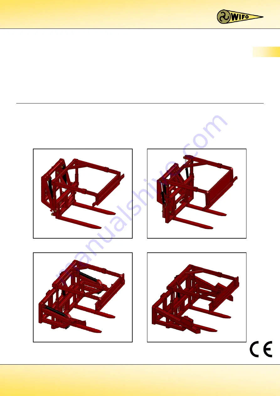
Содержание K75A

Страница 1: ...gebeintumerdyk 37 9172 GP Ferwert Holland Telefoon 0031 518411318 Telefax 0031 518411563 www wifo nl email info wifo nl Manual and safety instructions K75A K75B K80 K85 Forward tipping box rotator GB...

Страница 2: ......

Страница 3: ...DATA 9 2 2 K75A 11 2 2 1 Parts list 11 2 3 K75B 12 2 3 1 Parts list 12 2 3 2 Commissioning the K75A and K75B box rotators 13 2 4 K80 15 2 4 1 Parts list 15 2 5 K85 16 2 5 1 Parts list 16 2 5 2 Commiss...

Страница 4: ...nges and improvements deemed necessary without prior notice Please read the manual thoroughly and observe the safety procedures before putting the unit into operation Contact your dealer for any furth...

Страница 5: ...utions The following safety instructions apply to all types of WIFO forward tipping box rotators No distinction is made with regard to the type of lifting vehicle used This symbol is used for all impo...

Страница 6: ...upper clamp using the clamping cylinder before picking up the box with the box rotator Distribute the load as evenly as possible over the forks Keep the load as low as possible during transportation...

Страница 7: ...Place the rotator on its back on a flat stable surface after it has been removed from the forklift truck mast for storage Ensure that the operating levers for tipping and clamping cannot be confused...

Страница 8: ...arious safety stickers on the machine Be aware of the hazards they warn you to look out for Replace any loose illegible or missing stickers Figure 1 2 1 Location of safety stickers for K75A Figure 1 2...

Страница 9: ...lifting mast The box rotator must in no circumstances be used for the carriage of persons ATTENTION The capacity of the reach truck must exceed the total mass of the forward tipping box rotator the bo...

Страница 10: ...bserve the local regulations in terms of accident prevention safety traffic and transport 6 Only trained personnel with knowledge of the possible hazards have permission to work with on the machine 7...

Страница 11: ...dth 1300 mm 1600 mm Tipping angle1 110 180 110 180 Type K80 1200 K80 1400 K80 1600 K80 1800 Max carrying capacity 2500 kg 2500 kg 2500 kg 2500 kg Weight 580 kg 610 kg 640 kg 670 kg Max working pressur...

Страница 12: ...00 Max carrying capacity 2500 kg 2500 kg 2500 kg 2500 kg Weight 700 kg 725 kg 745 kg 765 kg Max working pressure 18 Mpa 180 bar 18 Mpa 180 bar 18 Mpa 180 bar 18 Mpa 180 bar Centre of gravity 625 mm 62...

Страница 13: ...ston rod side pin 4 Upper clamp 14 Tipping cylinder piston rod side washer 5 Upper clamp valve 15 Clamping cylinder bush side pin 6 Upper clamp slide tube 16 Clamping cylinder piston rod side pin 7 Su...

Страница 14: ...side pin 4 Upper clamp 14 Tipping cylinder piston rod side washer 5 Upper clamp valve 15 Clamping cylinder bush side pin 6 Upper clamp slide tube 16 Clamping cylinder piston rod side pin 7 Support le...

Страница 15: ...raulic hoses are connected a Electrically controlled reversing valve Connect the hydraulic supply discharge hoses to the dual action connection on the fork carrier Install the supplied switch so that...

Страница 16: ...h the clamping cylinder in its extended position the upper clamp will now pass around 10 through the 90 position This is sufficient to clamp the box 2 With the back of the box against the tipping fram...

Страница 17: ...per clamp slide in frame 14 Rotating point pin 5 Upper clamp 15 Cylinder washer 6 Clamping cylinder DW 50 30 330 16 Rotary pin 7 Category II top pin 17 Bump rubber 8 Clamping cylinder pin 18 Bump rubb...

Страница 18: ...n 18 Cover plate 6 Upper clamp adjustment beam 19 Tipping cylinder pin 7 Tipping cylinder DW 60 35 280 20 Washer 8 Clamping cylinder DW 50 30 330 21 Locking ring 9 Locking plate 22 Rack 10 FEM II III...

Страница 19: ...to the fork carrier profile with the FEM II profile above using the 9x11 pins and retaining clips 9 Check to make sure the hydraulic hoses are clean before connecting them to the rapid action couplin...

Страница 20: ...the clamping cylinder in its extended position the upper clamp will now pass around 10 through the 90 position This is sufficient to clamp the box 2 With the back of the box against the tipping frame...

Страница 21: ...th electro hydraulic valve Table 2 6 1 Parts list for K75A K75B K80 K85 connections Number Description Note 4 hose model 1 Feed through block 4 hose connection Electrically operated model 2 Electro hy...

Страница 22: ...Supply discharge hoses to clamping cylinder HYLR060031WW90 Hose to hose connector HYLR080031WW90 Rotating cylinder seal kit 779283 Clamping cylinder seal kit 7792823 Model without electrical control...

Страница 23: ...manual prior to any maintenance to the machine Turn off the engine and remove the key from the ignition while maintenance is carried out on the machine Regularly check the hydraulic system for any lea...

Страница 24: ...mit switch See figure 3 2 1 If the upper clamp fails to open in its horizontal position check whether the limit switch is operated If not the limit switch must be raised to the point where it does ope...

Страница 25: ...operate 1 Check that the tipping frame is horizontal and resting on its bump rubbers 2 Loosen the adjusting tube bolt and locknut See figure 3 2 3 3 Bring the stop to the correct height so that it co...

Страница 26: ......

Страница 27: ......

Страница 28: ...ngen van de Machinerichtlijn Richtlijn 2006 42 EG zoals laatstelijk gewijzigd en de nationale wetgeving ter uitvoering van deze richtlijn Is in conformity with the provisions of the Machine Directive...

Отзывы: