12
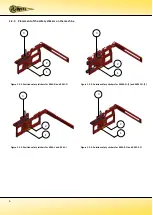
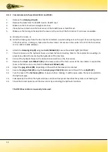
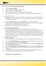
2.2.2 Commencement of operation K54A-I and K54C-I
1.
Remove the
clamping
strip
(2)
.
2.
Remove the forks from the forklift truck or forklift mast.
3.
Make sure the fork carrier is straight and clean.
4.
Place the box rotator onto the fork carrier of the forklift truck or forklift mast.
5.
Make sure the locking cam slots into the recess in the centre of the fork carrier. If no recess is available:
a)
Grind such a recess, or
b)
Grind the locking cam from the box rotator and attach a sound locking cam on the spot of an existing recess
in the fork carrier. In doing so, make sure the box rotator sits secure in the centre in front of the fork carrier,
so it is unable to slide sideways.
6.
Attach the
clamping strip (8)
using two
bolts M16x60 (3)
. Secure these bolts tight! (140 Nm)!
7.
Check to make sure the hydraulic hoses are clean before connecting them to the rapid-action couplings, to
prevent any debris from entering the hydraulics of the machine.
8.
Connect the hydraulic hoses to the dual-action connection on the fork carrier.
9.
Remove the
check nuts M16x25 (25)
in the lower plate of the fork carrier of the box rotator. Suspend the
forks to the fork carrier and attach the
check nuts M16x25 (25)
.
10.
Adjust the
plug-in fork (28)
, depending on the width of the boxes to be rotated.
11.
Secure the
plug-in fork (28)
using the
lock pin plug-in fork (26)
and secure this with the
r-clip Ø4
(27)
.
12.
Turn the lever of the
ball valve (29)
so it opens, before rotating. It will be open when the lever is parallel to
the hydraulic pipe.
13.
Subsequently check that the hydraulic hoses can move freely and check that the system is not leaking oil.
14.
Check the correct operation of the box rotator by controlling the hydraulic functions.
The WIFO box rotator is now ready to be used.
Содержание K54A-I
Страница 2: ......
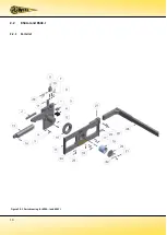
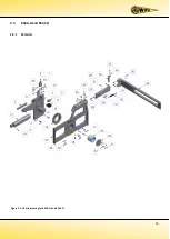
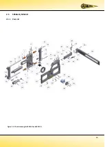
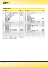
Страница 12: ...10 2 2 K54A I and K54C I 2 2 1 Parts list Figure 2 2 1 Parts drawing for K54A I and K54C I...
Страница 15: ...13 2 3 K54A O and K54C O 2 3 1 Parts list Figure 2 3 1 Parts drawing for K54A O and K54C O...
Страница 18: ...16 2 4 K54A Z O K54C Z O 2 4 1 Parts list Figure 2 4 1 Parts drawing for K54A Z O and K54C Z O...
Страница 21: ...19 2 5 SK54A O SK54C O 2 5 1 Parts list Figure 2 5 1 Parts drawing for SK54A O and SK54C O...
Страница 29: ......
Страница 30: ......
Страница 31: ......


