8. June 2010
1
*00679.A1
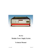
PL512
Modular Power Supply System
Technical Manual
Страница 1: ...8 June 2010 1 00679 A1 PL512 Modular Power Supply System Technical Manual...
Страница 2: ...50 IEC 60950 UL 60950 All devices are intended for operation in control cabinets or in closed areas The LAN connection and all wire connections between the different system parts must be done via shie...
Страница 3: ...gen harmonics EN 61 000 3 3 1995 Corr 1997 A1 2001 Spannungsschwankungen flicker 3 EN 61 000 6 2 2001 St rfestigkeit EMB immunity EN 61 000 4 6 1996 A1 2001 HF Einstr mung injected HF currents EN 61 0...
Страница 4: ...Function of the Switches 7 2 9 3 Main Operating Modes and Associated Submenus 8 2 10 Power Output and Sense Connections 9 3 PL512 Control and Setup via USB 10 3 1 Installation 10 3 2 The Main Window...
Страница 5: ...mensions 24 Figure 7 3 Two Channels Parallel 25 Figure 7 4 Three Channels Parallel 25 Figure 7 5 Four Channels Parallel 25 Tables Table 1 AC Mains Input Connector Pin Assignment 2 Table 2 USB Connecto...
Страница 6: ...oftware Ethernet connection IEEE 802 3 10BASE T and IEEE 802 3u 100BASE TX WWW Server integrated full control via SNMP protocol OPC server available Three different voltage regulation modes programmab...
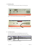
Страница 7: ...le plug STAK3N with the locking retainer STASI3 AC Input Pin Signal Comment 1 Phase 2 Return Neutral Cable wire color black or brown wire Cable wire color blue 3 unused Earth Protective Earth Safety G...
Страница 8: ...ector RJ45 Socket Pin Signal Comment 1 TX 2 TX 3 RX 4 GND 1 5 GND 1 6 RX 7 GND 2 8 GND 2 Table 3 Ethernet Connector Pin Assignment This is the standard NIC configuration You need a 1 1 cable to connec...
Страница 9: ...erved 10 NC reserved 23 NC reserved 11 NC reserved 24 NC reserved 12 NC reserved 25 GND Ground of the aux supply connected to USB ground 13 POWER_INHIBIT Inhibit input Table 4 Global Reset Connector P...
Страница 10: ...lock U6 20 Interlock U6 8 Interlock U7 21 Interlock U7 9 Interlock U8 22 Interlock U8 10 Interlock U9 23 Interlock U9 11 Interlock U10 24 Interlock U10 12 Interlock U11 25 Interlock U11 13 reserved Ta...
Страница 11: ...lobal Stop and Start Connector Pin Assignment The signals shall be connected by a dry contact e g relay and must not be connected to other potentials The input has an internal 330 pull up resistor to...
Страница 12: ...dure You will use the following switches of the PL512 Symbol Description Remarks P Push Power switch up ON Main power supply is off Switch the power supply on All power channels are off Display shows...
Страница 13: ...Change the value M or M 196 168 91 94 Accept change to next item P 196 168 91 94 Accept change to next item P 196 168 91 94 Accept change to next item P 196 168 91 94 Ready back to submenu selection...
Страница 14: ...ge TCP IP negotiation settings TCPIPnegotiation AutoNegotiation Display of the ethernet hardware address MAC This address is written at the type plate too TCPIP MAC Addres 0050 C22D C231 Change the TC...
Страница 15: ...L512 Control and Setup via USB The PL512 can be controlled with the MUSEcontrol software Without the Display option this is the only way to change the network TCP IP settings The USB interface is prim...
Страница 16: ...d hardware and ask to connect to Windows Update Select No and click Continue Then accept the Automatic install the software selection by clicking continue Now the USB driver software be installed To a...
Страница 17: ...group 1 for channels 0 5 and group 2 for channels 6 11 SelectOutput Select the next existing channel for the other dialogs The current channel is displayed at the title bar DVM Opens a large window s...
Страница 18: ...igital value of the most critical point of the power module is displayed The power of the load and the output power of the module are calculated values In the Nominal Values group the nominal values o...
Страница 19: ...els with the same group number off switch all channels of the power supply off The Identification group contains just a single item the group number of the channel Many SNMP network commands can addre...
Страница 20: ...g MIB file WIENER CRATE MIB txt If you are new to SNMP the www Net SNMP org website is a good start 6 OPC Server A server according to OPC Data Access V2 05 is optional available OPC OLE for Process C...
Страница 21: ...nning of the network and registration of communication stations restricting access rights by the underlying Microsoft DCOM The details of the OPC server can be found in the manual delivered with the O...
Страница 22: ...ICONTACT The arrangement is the same as at the power box Starting from left with U0 and positive outputs up negative outputs down Each sense lines of four output channels are connected to an eightfold...
Страница 23: ...V 100 mV 50 75 load change other 0 7 50 75 load change Recovery Time MDC M 2 8V 1 0 2 ms 0 1 0 5 ms 50 75 load change MDC M 5 16V 7 24V 1 0 0 ms 0 1 1 0 ms 50 75 load change MDC M 30 60V 1 0 5 ms 0 1...
Страница 24: ...group or channel wise programmable after overload overheat overvoltage undervoltage Interlock input optional Efficiency per Module 65 2V 81 5V 85 7V 87 12V 90 48V at nominal input voltage M T B F coo...
Страница 25: ...pins 80A parallel used for higher currents 3 x 9pin Sub D for sensing each for 4 channels Dimensions w h d 434 mm x 132 mm x 325 mm Weight 31 5 kg Accessories 19 Power Bin for plug in MARATON power su...
Страница 26: ...dules can be used without external ventilation integrated fans Module Type Channels per Module Optimal Voltage Range Peak Output Current Continuous Output Power MDH 2 2V 7V 8V 2 30A 2 210W MDH 2 5 7V...
Страница 27: ...general definition usable for different types of crates some items may be not implemented in the real hardware Here the not relevant parts are omitted The wiener OID is located at iso 1 org 3 dod 6 i...
Страница 28: ...GER outputAdjustVoltage 11 Range 128 127 RW Opaque outputCurrent 12 Textual Convention Float Size 7 RW INTEGER outputSupervisionBehavior 15 Range 0 65535 RW Opaque outputSupervisionMinSenseVoltage 16...
Страница 29: ...es public 1 private 2 admin 3 guru 4 RW String snmpCommunityName 2 Size 0 14 RW INTEGER snmpPort 2 powersupply 6 R String psSerialNumber 2 Textual Convention DisplayString Size 0 255 R INTEGER psOpera...
Страница 30: ...n one contact pair use the current bars to connect each option For best operation it is necessary to connect the parallel outputs together as near as possible at the power supply site For 200A 4 fold...
Страница 31: ...8 June 2010 26 00679 A1...
Страница 32: ...8 June 2010 27 00679 A1 Figure 7 3 Two Channels Parallel Figure 7 4 Three Channels Parallel Figure 7 5 Four Channels Parallel...