background image

1

W10680146A

W10680147A-SP

Table of Contents

DRYER SAFETY ................................................................

2

INSTALLATION REQUIREMENTS ....................................

4


Tools and Parts .................................................................... 4

LOCATION REQUIREMENTS ..................................................... 5

ELECTRICAL REQUIREMENTS - U.S.A. ONLY ........................ 6

ELECTRIC DRYER POWER HOOKUP-CANADA ONLY ........... 7

GAS DRYER POWER HOOKUP - U.S.A. AND CANADA .......... 7

INSTALL LEVELING LEGS .......................................................... 9

MAKE ELECTRICAL CONNECTION - U.S.A. ONLY ............... 10

MAKE GAS CONNECTION - U.S.A. AND CANADA ................ 16

VENTING .................................................................................... 16


Venting Requirements ....................................................... 16


Plan Vent System ............................................................... 17


Install Vent System ............................................................ 18

CONNECT INLET HOSES ......................................................... 18

CONNECT VENT ....................................................................... 20

LEVEL DRYER ........................................................................... 20

COMPLETE INSTALLATION CHECKLIST ............................... 21

REVERSE DOOR SWING .......................................................... 22


INSTALLATION NOTES

Date of purchase:

 _________________________________

Date of installation:

 _______________________________

Installer:

 ________________________________________

Model number:

 ___________________________________

Serial number:

 ___________________________________

Date d’achat :

 _____________________________________

Date d’installation :

 ________________________________

Installateur :

 ______________________________________

Numéro de modèle :

 ________________________________

Numéro de série :

 __________________________________

NOTES CONCERNANT L’INSTALLATION

Table des matières

SÉCURITÉ DE LA SÉCHEUSE ........................................

26

EXIGENCES D’INSTALLATION .......................................

28


Outillage et pièces ............................................................. 28

EXIGENCES D’EMPLACEMENT ............................................... 29

RACCORDEMENT DE LA SÉCHEUSE  

ÉLECTRIQUE – CANADA SEULEMENT ................................... 30

RACCORDEMENT ÉLECTRIQUE DE LA SÉCHEUSE À GAZ - 

ÉTATS-UNIS ET CANADA ......................................................... 31

INSTALLATION DES PIEDS DE NIVELLEMENT ...................... 33

RACCORDEMENT AU GAZ - ÉTATS-UNIS ET CANADA ........ 34

L’EVACUATION........................................................................... 34


Exigences concernant l’evacuation ................................. 34


Planification des circuits de conduits .............................. 35


Installation du système d’évacuation ............................... 36

RACCORDEMENT DES TUYAUX DE VIDANGE ...................... 37

RACCORDEMENT DU SYSTÈME D’ÉVACUATION ................. 38

ÉTABLIR L’APLOMB DE LA SÉCHEUSE .................................. 39

ACHEVER L’INSTALLATION LISTE DE VÉRIFICATION  .......... 39

INVERSION DU SENS D’OUVERTURE DE LA PORTE ............ 40

Gas and Electric Dryer Installation Instructions

Instructions d’installation – Sécheuse à gaz et électrique 

Para obtener acceso al “Instrucciones de instalación” en español, o para obtener información  

adicional acerca de su producto, visite: www.whirlpool.com 

Tenga listo su número de modelo completo. Puede encontrar el número de modelo  

y de serie dentro de la cavidad superior de la puerta.

Содержание WGD8500DC

Страница 1: ... de modèle _________________________________ Numéro de série ___________________________________ NOTES CONCERNANT L INSTALLATION Table des matières SÉCURITÉ DE LA SÉCHEUSE 26 EXIGENCES D INSTALLATION 28 Outillage et pièces 28 EXIGENCES D EMPLACEMENT 29 RACCORDEMENT DE LA SÉCHEUSE ÉLECTRIQUE CANADA SEULEMENT 30 RACCORDEMENT ÉLECTRIQUE DE LA SÉCHEUSE À GAZ ÉTATS UNIS ET CANADA 31 INSTALLATION DES PI...

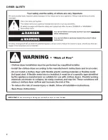
Страница 2: ...2 DRYER SAFETY IMPORTANT When discarding or storing your old clothes dryer remove the door ...

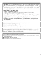
Страница 3: ...3 ...

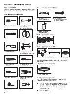
Страница 4: ...pe wrench 8 203 mm or 10 254 mm adjustable wrench for gas connections Pipe joint compound resistant to LP gas Plastic putty knife INSTALLATION REQUIREMENTS Leveling legs 4 Tape measure Pliers Parts supplied steam models Y connector Short inlet hose 5 1 52 m inlet hose Rubber washer Parts needed steam models Parts package is located in dryer drum Check that all parts are included If using a power s...

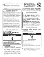
Страница 5: ...temperatures below 45 F 7 C Lower temperatures may cause dryer not to shut off at end of automatic sensor cycles resulting in longer drying times NOTE No other fuel burning appliance can be installed in the same closet as a dryer DRYER DIMENSIONS INSTALLATION CLEARANCES For each arrangement consider allowing more space for ease of installation and servicing spacing for companion appliances and cle...

Страница 6: ...ill be using and follow the instructions provided for it here This dryer is manufactured ready to install with a 3 wire electrical supply connection The neutral ground conductor is permanently connected to the neutral conductor white wire within the dryer If the dryer is installed with a 4 wire electrical supply connection the neutral ground conductor must be removed from the external ground conne...

Страница 7: ...s final location If using a replacement power supply cord it is recommended that you use Power Supply Cord Replacement Part Number 9831317 For further information please reference service numbers located in Assistance or Service section of your Use and Care Guide GROUNDING INSTRUCTIONS SAVE THESE INSTRUCTIONS For a grounded cord connected dryer This dryer must be grounded In the event of malfuncti...

Страница 8: ...are using Natural gas do not use copper tubing Lengths over 20 ft 6 1 m should use larger tubing and a different size adapter fitting If your dryer has been converted to use LP gas 3 8 LP compatible copper tubing can be used If the total length of the supply line is more than 20 ft 6 1 m use larger pipe NOTE Pipe joint compounds that resist the action of LP gas must be used Do not use TEFLON tape ...

Страница 9: ...r must be disconnected from the gas supply piping system during pressure testing at pressures greater than 1 2 psi DRYER GAS PIPE The gas pipe that comes out through the rear of your dryer has a 3 8 male pipe thread INSTALL LEVELING LEGS Prepare dryer for leveling legs 1 Firmly grasp dryer body not console panel and gently lay dryer down on back cardboard corner posts IMPORTANT If laying dryer on ...

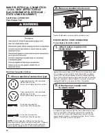
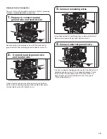
Страница 10: ...ct wire connection 2 Remove terminal block cover Remove hold down screw and terminal block cover Put power supply cord through the strain relief Be sure that the wire insulation on the power supply cord is inside the strain relief The strain relief should have a tight fit with the dryer cabinet and be in a horizontal position Do not further tighten strain relief screws at this point Attach power s...

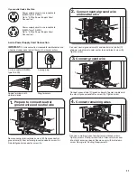
Страница 11: ... B Remove neutral ground wire E from external ground conductor screw A Reinstall ground conductor screw A B A E Prepare to connect neutral ground wire and neutral wire 1 B E C Connect neutral ground wire and neutral wire 2 Connect neutral ground wire E and neutral wire white C of power supply cord under center terminal block screw B Tighten screw Connect remaining wires 4 Connect remaining wires t...

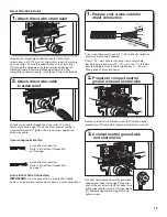
Страница 12: ...ng wires Connect remaining wires to outer terminal block screws Tighten screws Finally reinsert tab of terminal block cover into slot of dryer rear panel Secure cover with hold down screw Now go to Venting Requirements 2 Connect neutral wire Connect neutral wire white or center C of power supply cord to center terminal block screw B Tighten screw B C Remove center terminal block screw B B 1 Remove...

Страница 13: ...nection on this page If your wiring looks like this 4 wire Direct Wire Connection IMPORTANT A 4 wire connection is required for mobile homes and where local codes do not permit 3 wire connections Direct wire cable must have 5 ft 1 52 m of extra length so dryer may be moved if needed Strip 5 127 mm of outer covering from end of cable leaving bare ground wire at 5 127 mm Cut 11 2 38 mm from remainin...

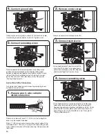
Страница 14: ...ct wire cable must have 5 ft 1 52 m of extra length so dryer may be moved if needed Strip 31 2 89 mm of outer covering from end of cable Strip insulation back 1 25 mm If using 3 wire cable with ground wire cut bare wire even with outer covering Shape wire ends into hooks 1 25 mm 3 89 mm 1 Prepare your 3 wire cable for direct connection Connect remaining wires 4 Place hooked ends of remaining direc...

Страница 15: ...onnect neutral ground wire E and neutral wire white or center wire C of power supply cord or cable under center terminal block screw B Tighten screw Connect remaining wires 3 Place hooked ends of remaining wires under outer terminal block screws hooks facing right Tighten screws A G Connect external ground wire 4 Connect a separate copper ground wire G from the external ground conductor screw A to...

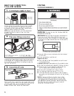
Страница 16: ...tem and make sure exhaust hood is not plugged with lint Replace plastic or metal foil vents with rigid metal or flexible metal vents Review Vent System Chart and if necessary modify existing vent system to achieve best drying performance VENTING Connect gas supply to dryer 1 Remove red cap from gas pipe Using a wrench to tighten connect gas supply to dryer Use pipe joint compound on threads of all...

Страница 17: ...m from ground or any object that may obstruct exhaust such as flowers rocks bushes or snow Acceptable Style Optional exhaust installations PLAN VENT SYSTEM Recommended exhaust installations Typical installations vent the dryer from the rear of the dryer Other installations are possible B B C D E F G H A A Dryer B Elbow C Wall D Exhaust hood E Clamps F Rigid metal or flexible metal vent G Vent leng...

Страница 18: ...m Chart to determine type of vent material and hood combinations acceptable to use NOTE Do not use vent runs longer than those specified in Vent System Chart Exhaust systems longer than those specified will Shorten life of dryer Reduce performance resulting in longer drying times and increased energy usage Vent System Chart Number of 90 elbows Type of vent Angled hoods 1 4 3 2 0 Rigid metal Rigid ...

Страница 19: ...er cold inlet hose to other side of Y connector Screw on coupling by hand until it is seated on connector Using pliers tighten the couplings an additional two thirds turn NOTE Do not overtighten Damage to the coupling can result 57 8 150 mm 41 2 115 mm Attach long hose to dryer fill valve and tighten coupling 5 Attach other end of long hose to fill valve at bottom of dryer back panel Screw on coup...

Страница 20: ...t outlet in dryer If connecting to existing vent make sure vent is clean Dryer vent must fit over dryer exhaust outlet and inside exhaust hood Check that vent is secured to exhaust hood with a 4 102 mm clamp Move dryer to final location 2 Move dryer to final location Avoid crushing or kinking vent Level Dryer 1 Adjust leveling legs 2 If dryer is not level prop up using a wood block Use wrench to a...

Страница 21: ...of scale through the water system in the dryer Over time the buildup of lime scale may clog different parts of the water system which will reduce product performance Excessive scale buildup may lead to the need for certain part replacement or repair All Models q Select a Timed Dry heated cycle and start dryer Do not select Air Only Temperature setting If dryer will not start check the following Co...

Страница 22: ...ing up Remove remaining two loose screws from dryer front panel Set the hinge screws off to the side for reinstalling the door 6 Install 2 plastic plugs A into screw holes where the hinges were removed in Step 4 Reverse the strike 1 Remove the door strike A from the dryer door opening 2 Remove the cosmetic screw B opposite the door strike A A Door strike B Cosmetic screw 3 Reinstall the door strik...

Страница 23: ...emove the inner door by taking a plastic putty knife to separate the sides and bottom of the dryer door and trim There are 2 snaps on left right and bottom of door Insert the putty knife next to the snaps 4 When you have the door separated from the frame use a putty knife and lift up in the center tab and then pull door towards you and out Lay the door on a flat covered surface with the inside of ...

Страница 24: ...he right side of the door 6 Remove the door hinges and set off to the side 8 Lift door up and rotate trim pieces to the opposite side they were removed from Then screw trim pieces back in 5 Remove the door strike plug with a flathead screw driver Remove door strike by pinching the clips from the inside door panel and then rotate and push out the front Insert door strike on the other side of dryer ...

Страница 25: ...the hinges lined up with the hinge holes 11 Install 6 hinge screws and the other 4 screws 12 Install hinge covers and plugs Hinge covers will go in sideways to then rotate 90 and snap into place 13 Hang door by placing screw heads into top slotted holes of hinges and slide door down Align bottom screw holes in hinge and door Install two bottom screws Tighten all hinge screws ...

Страница 26: ...26 SÉCURITÉ DE LA SÉCHEUSE IMPORTANT Pour mettre l ancienne sécheuse au rebut ou pour la remiser enlever la porte ...

Страница 27: ...27 ...

Страница 28: ...eur Connecteur en Y Tuyau d alimentation court Tuyau d arrivée d eau de 5 1 52 m Rondelle en caoutchouc Pièces nécessaires modèles vapeur Retirer le sachet de pièces du tambour de la sécheuse Vérifier que toutes les pièces sont présentes Tournevis Phillips n 2 Cisaille de ferblantier pour l installation d un nouveau conduit Outils nécessaires pour les installations à gaz Clé à tuyau de 8 203 mm ou...

Страница 29: ...s valves de remplissage et une pression d eau de 20 à 100 lb po2 137 9 à 689 6 kPa L alimentation en eau de la laveuse peut être utilisée avec le connecteur en Y et le tuyau court fournis IMPORTANT Ne pas installer remiser ou faire fonctionner la sécheuse à un emplacement où elle sera exposée à de l eau des intempéries ou à des températures inférieures à 45 F 7 C À des températures inférieures la ...

Страница 30: ...t l entretien Un espace supplémentaire peut être requis pour les moulures de porte et de plancher et pour les plinthes Un espace supplémentaire de 1 25 mm de tous les côtés de la sécheuse est recommandé pour réduire le transfert du bruit Un espace supplémentaire doit être envisagé de tous les côtés de la sécheuse afin de réduire le transfert de bruit Pour installation dans un placard avec porte on...

Страница 31: ...che de branchement fournie avec la sécheuse si la fiche ne correspond pas à la configuration de la prise de courant demander à un électricien qualifié d installer une prise de courant appropriée RACCORDEMENT ÉLECTRIQUE DE LA SÉCHEUSE À GAZ ÉTATS UNIS ET CANADA SPÉCIFICATIONS ÉLECTRIQUES Une source d alimentation de 120 V 60 Hz CA uniquement de 15 ou 20 ampères et protégée par fusible est nécessair...

Страница 32: ...uit et le joint conique de 3 8 C Connecteur obturé filetage NPT de 1 8 ou plus D Canalisation d alimentation en gaz filetage NPT de 1 2 E Robinet d arrêt du gaz Option 2 méthode alternative Conduit d aluminium ou de cuivre approuvé La canalisation doit comprendre un connecteur obturé filetage NPT de 1 8 ou plus accessible pour le raccordement de l instrument de mesure immédiatement en amont de la ...

Страница 33: ...ONS DE L ALIMENTATION DU BRÛLEUR Altitudes supérieures à 2 000 pi 610 m Si la sécheuse doit être utilisée à une altitude supérieure à 2 000 pi 610 m on doit réduire le débit thermique du brûleur indiqué sur la plaque signalétique de 4 pour chaque tranche de 1 000 pi 305 m d augmentation de l altitude Épreuve sous pression de l alimentation en gaz La sécheuse doit être déconnectée du système de can...

Страница 34: ...tion tel qu indiqué dans les Tableaux des systèmes d évacuation 4 102 mm Conduit d évacuation en métal lourd de 4 102 mm Raccorder l alimentation en gaz à la sécheuse 1 Retirer le capuchon rouge de la canalisation de gaz À l aide d une clé pour serrer raccorder l alimentation en gaz à la sécheuse Utiliser un composé d étanchéité des tuyauteries sur tous les filetages des raccords mâles non conique...

Страница 35: ...ation ne doit pas être raccordé ou fixé avec des vis ou tout autre dispositif de serrage qui se prolongerait à l intérieur du conduit et retiendrait la charpie Ne pas utiliser de ruban adhésif pour conduit Une mauvaise évacuation de l air peut causer de l humidité et une accumulation de charpie à l intérieur de la maison ce qui peut provoquer Dommages par l humidité aux boiseries meubles peinture ...

Страница 36: ...RQUE Ne pas utiliser de conduits de longueur supérieure à la valeur spécifiée dans le tableau des systèmes d évacuation Si la longueur du circuit est supérieure à la valeur spécifiée dans le tableau on observera Un cycle de vie réduit de la sécheuse Une réduction du rendement avec temps de séchage plus longs et une plus grande consommation d énergie Tableau des systèmes d évacuation Nombre de coud...

Страница 37: ... la laveuse Retirer l ancien joint de caoutchouc du tuyau d arrivée d eau et le remplacer par un joint de caoutchouc neuf Fermer l eau froide retirer et remplacer le joint de caoutchouc 1 Serrer les raccords 3 Terminer le serrage des raccords de deux tiers de tour supplémentaire avec une pince REMARQUE Ne pas serrer excessivement Le raccord risque d être endommagé Fixer le tuyau court et le raccor...

Страница 38: ...final 2 Placer la sécheuse à son emplacement final Éviter d écraser ou de déformer le conduit d évacuation 57 8 150 mm 41 2 115 mm Fixer le long tuyau à l électrovanne de remplissage de la sécheuse et serrer les raccords 5 Fixer l autre extrémité du long tuyau à l électrovanne située au bas du panneau arrière de la sécheuse Visser le raccord à la main jusqu à ce qu il repose sur le connecteur de l...

Страница 39: ...lisation et d entretien Modèles électriques q Pour une installation avec cordon d alimentation brancher sur une prise reliée à la terre Pour une installation à raccordement direct mettre l appareil sous tension Modèles à gaz q S assurer que l alimentation en gaz est ouverte q Vérifier qu il n y a pas de fuites Modèles avec génération de vapeur uniquement q Vérifier que les robinets d eau sont ouve...

Страница 40: ... sur la gauche de la sécheuse là où les charnières ont été retirées à l étape 4 A B A B A A A A Outillage nécessaire Tournevis TORX T25 de 8 20 cm min de long Tournevis à lame plate Couteau à mastic en plastique Tournevis Phillips n 2 TORX et T25 sont les marques de commerce déposées de Acument Intellectual Properties LLC 5 Retirer les 2 chevilles de plastique A situées à l extérieur de l ouvertur...

Страница 41: ...ête plate Elles sont munies d une ouverture pour y insérer le tournevis et les extraire 2 Retirer les 10 vis de la porte de la sécheuse et les mettre de côté 3 Retirer la porte intérieure en séparant les côtés et le bas de la porte de la sécheuse et de la garniture à aide d un couteau à mastic en plastique 2 attaches sont situées sur la gauche sur la droite et sur le bas de la porte Insérer le cou...

Страница 42: ... porte et les mettre de côté 8 Soulever la porte et faire pivoter les garnitures du côté opposé par rapport à leur emplacement initial Ensuite revisser les garnitures en place 5 Retirer la cheville de la gâche de la porte avec un tournevis à tête plate Retirer la gâche de la porte en pinçant les agrafes de l intérieur du panneau de la prote puis en les faisant pivoter et en appuyant sur l avant In...

Страница 43: ...taller les 6 vis de charnière et les 4 autres vis 12 Installer les couvre charnières et les chevilles Les couvre charnières s insèrent de côté puis se pivotent à 90 pour s emboîter en place 13 Suspendre la porte en insérant les têtes de vis dans les trous de fente supérieurs des charnières et en glissant la porte vers le bas Aligner les trous de vis inférieurs de la charnière et de la porte Fixer ...

Страница 44: ...W10680146A W10680147A SP 2014 All rights reserved Tous droits réservés 05 14 Printed in U S A Imprimé aux É U ...

Отзывы: