background image

Содержание Packaged Terminal Air Conditioner

Страница 1: ...ation Requirements t 7 FRONT COVER SIDE MOUNT KIT INSTALLATION INSTRUCTIONS 20 CONTROLS 21 LIMITING TEMPERATURE RANGE 22 HEAT PUMP CHANGEOVER AND EMERGENCY HEAT CONTROL ADJUSTMENT 22 Heat pumps and emergency heat operation 22 FAN CYCLE SWITCH 23 OUTSIDE AIR VENT CONTROL 23 AIR DISCHARGE GRILLE 24 REMOTE WALL THERMOSTAT INSTALLATION INSTRUCTIONS 24 Installation Requirements 24 Location Requirements...

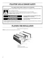
Страница 2: ...alert symbol and either the word DANGER or WARNING These words mean You can be killed or seriously injured if you don t immediately follow instructions You can be killed or seriously injured if you don t follow instructions All safety messages will tell you what the potential hazard is tell you how to reduce the chance of injury and tell you what can happen if the instructions are not followed PIA...

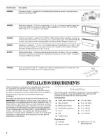
Страница 3: ...ve extension 4 in 10 2 cm deep anodized aluminum extension that attaches to the outside of the wall sleeve when the wall is thicker than 13 in 33 cm if no accessories are attached to the wall sleeve 123 4in 32 4 cm if a lateral duct is used 113 4in 29 8 cm if a subbase is used 4396592 4396597 Subbase provides unit support for walls less than 6 in 15 2 cm thick or for any wall structurally unable t...

Страница 4: ... instructions are intended as a general guide only and do not supersede any national or local codes in any way Compliance with all local state or national codes pertaining to this type of equipment should be determined prior to installation Read this entire instruction manual before starting the installation All models are designed for through the wall installation only IMPORTANT The installation ...

Страница 5: ...acrylic enamel Architectural louver is a replacement for the standard louver It consists of heavy gauge aluminum alloy in the following finishes clear extruded aluminum and dark bronze acrylic enamel Lateral duct adapter kit attaches to the PTAC PTHP and provides a transition to direct up to 35 of the total airflow to a secondary room either left or right of the PTAC PTHR Kit includes duct plenum ...

Страница 6: ...te the drain kit in the secondary area and cut away the foam insulation to allow access to the drain Do not locate the drain kit within 3 in 7 6 cm of the indoor side of the sleeve 1 NOTES Determine whether the drain will be located on the exterior of the wall internally in the wall cavity or internally in the room Internal drain Drain kit located inside the room will allow condensate to drain to ...

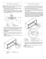
Страница 7: ...g tape from the gaskets and mount them on the curved side of one cover plate and one mounting plate Place the drain tube through the gasket and the mounting plate with the flange toward the wall sleeve Using 2 10 x _ 2in sheet metal screws provided attach the drain tube assembly to one of the 2 drain holes at the rear of the wall sleeve Position the large flange at the bottom of the sleeve facing ...

Страница 8: ...nstall chassis and outdoor grille IMPORTANT If additional support for the wall sleeve is required or the wall sleeve projects more than 8 in 20 3 cm into the room an accessory subbase must be used See Subbase Installation Instructions If a hole is to be cut into an existing wall to install the sleeve disconnect power to all wires within the wall Wall Opening Requirements Refer to the following ill...

Страница 9: ...ired by the installation of the drain kit Drill two 3 16 in holes through each side of the sleeve drilling only through the wall sleeve and not into the wall Locate one hole approximately 4 in 10 2 cm from the top and another hole 4 in 10 2 cm from the bottom of the sleeve where it will attach to the wall If the wall construction is wood screw the 4 10 x 1 in wood screws provided through the holes...

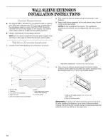
Страница 10: ...ve using 4 sheet metal screws provided NOTE Do not overtighten the screws The wall sleeve extension is aluminum and overtightening will strip out the holes 8 7 4 Wall sleeveextensions maximum of 3 may be used Run a bead of silicone sealant along the bottom mating surfaces of the wall sleeve and the wall sleeve extension Run this bead at least 3 in 7 6 cm up the side seams _5 mlmf Jy 1 Front edge 6...

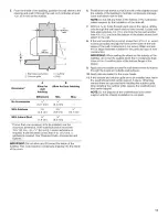
Страница 11: ...eeve unless required by the installation of the drain kit Drill two 3 16 in holes through each side of the sleeve drilling only through the wall sleeve and not into the wall Locate one hole approximately 4 in 10 2 cm from the top and another hole 4 in 10 2 cm from the bottom of the sleeve where it will attach to the wall If the wall construction is wood screw the 4 10 x 1 in wood screws provided t...

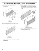
Страница 12: ...eads are inserted into the keyhole slots at the top of the wall sleeve Tighten the 2 screws 2 Wall sleeve 2 Weatherboard 3 Center support Insert 6 plastic grommets into the outdoor grille openings from the outside of the grille 2 5 Plastic handles 2 Plastic grommets 3 Condensate drain knockouts Insert the remaining screws into the remaining holes and into the grommets and tighten all screws 3 1 Pl...

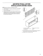
Страница 13: ...pports Position it with the condensate drain knockouts facing down From the inside of the building maneuver the louver through the wall sleeve Pull it toward you until the threaded studs are inserted into the 4 holes of the wall sleeve 4 5 Architectural louver 4 Interior side of wall sleeve 2 Condensate drain knockouts 5 Washer 3 Threaded stud 6 Nut While holding the louver with one hand place the...

Страница 14: ...apter 1 2 1 Install screw clips 4 Angle flange 2 Existing screw clips 5 Wall sleeve adapter 3 Wall sleeve 3 2 4 Insert the angle flange of the wall sleeve adapter over the bottom flange of the existing sleeve Align the top of the adapter with the top surface of the existing wall sleeve 1 2 1 Additional insulation pieces 2 Existing insulation CHASSISINSTALLATION 2 Remove the 2 chassis shipping brac...

Страница 15: ...iring must conform to the requirements of the National Electrical Code ANSI NFPA NO 70 latest edition in the United States and any state laws and local ordinances including plumbing or wastewater codes In Canada field wiring must conform to the Canadian electrical code PART I CSA STANDARD C22 1 1993 or current edition Local authorities having jurisdiction should be consulted before installation is...

Страница 16: ...l the chassis pigtail wires into the control box and remove the bushing from the hole The field supplied wires will be routed through this hole 1 2 6 Bushing 2 Control box Install field supplied conduit into the same hole as the original bushing for the chassis pigtail wires on the control box 1 Field supplied conduit 2 Control box 7 Connect the chassis pigtail wires to the incoming power supply w...

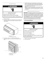
Страница 17: ... of packaging materials Electrical Shock Hazard Disconnect power before servicing Replace all parts and panels before operating Failure to do so can result in death or electrical shock Electrical Shock Hazard Electrically ground PTAC PTHP Connect ground wire to green pigtail lead Use copper wire for supply connection Correct wire gauge is shown in the chart below Failure to follow these instructio...

Страница 18: ...as shown 3 4 Junction box 2 Power supply wires Remove the PTAC PTHP front cover using the thumbscrews Remove the 4 screws holding the control box as shown 7 1 Junction box 2 Junction box cover 3 Right angle connector Insert one bushing provided into one end of the flexible conduit 5 Remove these screws 2 Do not remove these screws 3 Bushing Pivot the control box down pull the chassis pigtail wires...

Страница 19: ...ing power supply is in subbase proceed to the subbase instructions 13 Connect conduit wires black to black green to green white to white to the chassis pigtail wires using the UL listed wire nuts provided I 2 34 56 1 Black wire 4 Green wire 2 Black wire 5 White wire 3 Green wire 6 White wire 14 Route the flexible conduit from the bottom of the control box to the junction box 15 Connect conduit wir...

Страница 20: ...tom of each side bracket NOTE Do not remove these screws 3 1 Indent inside view 2 Front of front cover Remove the screw clip from the bottom of each side bracket Save it for reinstallation Side bracket screws loosen do not remove 5 Slide the appropriate mounting bracket onto the side bracket screws and tighten the screws 6 Install the screw clip onto the mounting bracket with the smooth side facin...

Страница 21: ...formance of the PTAC PTHP by turning the temperature control knob clockwise until it stops for maximum cooling and counterclockwise until it stops for maximum heating Experiment to find the setting that suits you best NOTE Cooling will not begin if the room temperature is below 60 F 15 6 C Heating will not begin if the room temperature is above 90 F 32 2 C Fan Control Set the fan control to the de...

Страница 22: ... coils At extremely low outdoor ambient temperatures the heat pump is automatically disabled and the PTHP operates solely on electric resistance heat Heat Control Adjustment The heating control is located behind the front cover on the right side panel of the chassis Its function is to allow you to set the outdoor temperature range in which the heat pump operates This control switches the unit heat...

Страница 23: ...ontrol is on the wall thermostat OUTSIDEAIRVENTCONTROL The vent control lever is located behind the front cover on the left side of the unit The unit is shipped with the vent control lever in the closed position and a locking screw in place The screw must be removed to operate the lever When the lever is Open back toward the wall outside air is mixed with indoor air When the lever is Closed forwar...

Страница 24: ...ng call for heating G Fan Continuous if the slider is in the Fan position otherwise on call for cooling or heating C common Common Terminal Constant R 24 V to the Constant directly from thermostat the transformer B Heat Pump Reversing Valve Made continuously when units Only the mode switch is in heating For best performance thermostat should be mounted Approximately 5 ft 152 4 cm from floor Close ...

Страница 25: ...terminals in accordance with the wiring diagram 1 Typical PTAC PTHP unit 2 Used for PTHP only 3 Wall thermostat 5 Route the 24 volt thermostat wire alongside the conduit or service cord to the location chosen for the thermostat 6 Separate the front housing and back plate of the thermostat 2 375 3 275 9 Secure back plate to wall with 2 anchors and screws provided making sure all wires extend throug...

Страница 26: ...d begin to operate within 5 minutes Temperature Display The thermostat will display room temperature until the or buttons are pressed The word SET appears when these buttons are pressed and the current set point is displayed If no buttons are pressed for 5 seconds the display will change back to show room temperature Mode button on Thermostat Press the MODE button on the thermostat to turn the PTA...

Страница 27: ...ents take precedence over the general instructions in this manual This kit is intended only for use with the subbase The switch must be installed in the subbase before the subbase is installed Electrical Shock Hazard Disconnect power before servicing Replace all parts and panels before operating Failure to do so can result in death or electrical shock 1 Disconnect power 2 Remove subbase access cov...

Страница 28: ...ion 9 Replace all covers f Ground wire to subbase ground lug SUBBASE KITINSTALLATIONINSTRUCTIONS Subbase Assembly Unpack and dispose of packaging materials If your wall thickness is less than 6 in 15 2 cm the subbase kit is required If wiring through the subbase connections must be made behind the front cover See Make Electrical Connections 3 4 5 End bracket 4 Front cover 2 Side skirt 5 Access cov...

Страница 29: ...des In Canada field wiring must conform to the Canadian electrical code PART I CSA STANDARD C22 1 1993 or current edition Local authorities having jurisdiction should be consulted before installation is made Such applicable regulations or requirements take precedence over the general instructions in this manual 1 Disconnect power 2 Remove the chassis from the wall sleeve if installed 4 Position th...

Страница 30: ...when transferring the measurement Example If measurement was 7 in 17 8 cm use the score mark that is at 6 in 10 Cut the skirts along the scored marks 11 Reattach the end brackets and side skirts to the subbase Adjust the side skirts until they touch the wall Tighten the screws 12 Attach the end brackets to the wall sleeve with 4 10 x _ 2 in screws provided 13 Adjust the leg bolts as needed to leve...

Страница 31: ...er 10 Replace all subbase covers 11 Reconnect power 265 volt power supply In 265 volt applications field supplied conduit and wires or the conduit and junction box accessory can be installed in the subbase along with the optional disconnect switch accessory r i Black L1 b_oOl _ _ _ i_ I Neutral r II White II _jj _ 2 3 4 5 Field Supplied Wiring 1 Disconnect switch if used 4 Wire nuts 2 Ground lug i...

Страница 32: ...wer 2 Route incoming power supply wires into the subbase behind the front cover 3 Route the field supplied black white and green wires through the field supplied conduit 4 Attach one conduit connector to the receptacle plate in the subbase 5 Connect the incoming L1 black wire and incoming neutral white wire to one side of the disconnect switch Connect the field supplied black wire and field suppli...

Страница 33: ... to the black wire in the conduit using UL listed wire nuts provided 8 Connect the incoming neutral white wire to the the white wire in the conduit using UL listed wire nuts provided 9 Connect the incoming green or bare ground wire and green wire in the conduit to the subbase ground lug 10 Reattach the PTAC PTHP front cover using the thumbscrews removed earlier 11 Replace all subbase covers 12 Rec...

Страница 34: ...ard Disconnect power before servicing Replace all parts and panels before operating Failure to do so can result in death or electrical shock 4 Remove the 4 screws and rotate the control panel open 5 1 Remove these screws 2 Do not remove these screws 3 Bushing Mount the desk control relay on the control box back wall with 2 screws provided 1 Disconnect power 2 Remove the front cover 3 Remove the th...

Страница 35: ...through the hole and connect them to the coil terminals of the desk control relay coil ii i ii i i iii i iiii i 1 White wire 2 Slack wire 8 Snap the strain relief bushing provided over the wire harness and insert it into the hole in the control box Be sure that there is enough wire slack inside the control box to rotate the control box fully opened Remote Thermostat Control on some models remote w...

Страница 36: ...ce 4 Reinstall the plastic front 5 Reconnectpowe_ Each desk control relay requires approximately 10 VA of power Terminal numbers are marked on the desk control relay If PTAC PTHP is 230 208 volt see Make Electrical Connections 230 208 Volt Power Supply Determine whether PTAC PTHP is equipped with standard or remote thermostat controls and see the appropriate section Standard Controls no remote wal...

Страница 37: ...osition and reinstall the 4 screws Make sure that all the wires are connected inside the control box Run the wires from the front desk and connect them to the relay coil harness Use the supplied wire nuts on this connection These wires connect to the front desk control switch IMPORTANT The installation of field wiring must conform to the requirements of the National Electrical Code ANSI NFPA NO 70...

Страница 38: ...ed edge of the deck and align the side with the outer edge of the cutoff flange Mark the location of the holes center punch and drill two 2 in holes through the flanges on each side 1 Seal plate 2 Holes in cutoff flanges 7 Using 4 unpainted screws screw the left and right seal plates to the cutoff flanges 8 Remove the discharge grille by removing the 6 screws from underneath the plastic front 1 Re...

Страница 39: ... toward the front of the duct adapter To decrease airflow to the side register position the deflector plate to the rear of the duct adapter 1 Front of duct adapter 2 Discharge grille 3 Air deflector 4 End view Complete Installation 1 2 Attach additional duct extensions using 4 painted screws each Cut the opening in the wall to 7V4in 18 4 cm high x 7_ 4in 18 4 cm wide The top of the duct will be ap...

Страница 40: ...e 1 Remove air filters by sliding filters up and out of front cover 2 3 Shake off loose debris into trash receptacle Use a vacuum cleaner to clean air filters If air filters are very dirty wash in warm water with a mild detergent Do not wash air filters in the dishwasher or use any chemical cleaners Air dry filters completely before replacing to ensure maximum efficiency 1 Remove air filters and c...

Страница 41: ... damage cover the fan motor control box and compressor terminals and make sure no water or other liquids get inside any of these parts 5 Carefully clean and hose out base pan condenser coil and evaporator coil Clean at least once a year or more often if the condenser and evaporator coils and base pan collect dirt sand leaves insects or algae Also clean if you detect an odor coming from the air con...

Страница 42: ...ity before noticing any cooling effect Has the cooling load been increased by additional devices such as computer equipment or has the room area been increased where the PTAC PTHP is located If conditions have changed the PTAC PTHP may not be able to cool and condition as effectively as previously planned Environmental Effects Heating Mode Is the PTAC PTHP properly sized to the room area and heat ...

Страница 43: ... service companies Whirlpool designated service technicians are trained to fulfill the product warranty and provide after warranty service anywhere in the United States To locate the Whirlpool designated service company in your area you can also look in your telephone directory Yellow Pages For further assistance If you need further assistance you can write to Whirlpool Corporation with any questi...

Страница 44: ...an or replace owner accessible air filters 2 Damage resulting from accident alteration misuse abuse fire floods acts of God improper installation not in accordance with local electrical and plumbing codes or use of products not approved by Whirlpool Corporation or Whirlpool Canada Inc 3 Replacement parts or repair labor costs for units operated outside the United States or Canada 4 Pickup and deli...

Отзывы: