Common Mode Rejection Ratio Tester | User manual
WHALETEQ
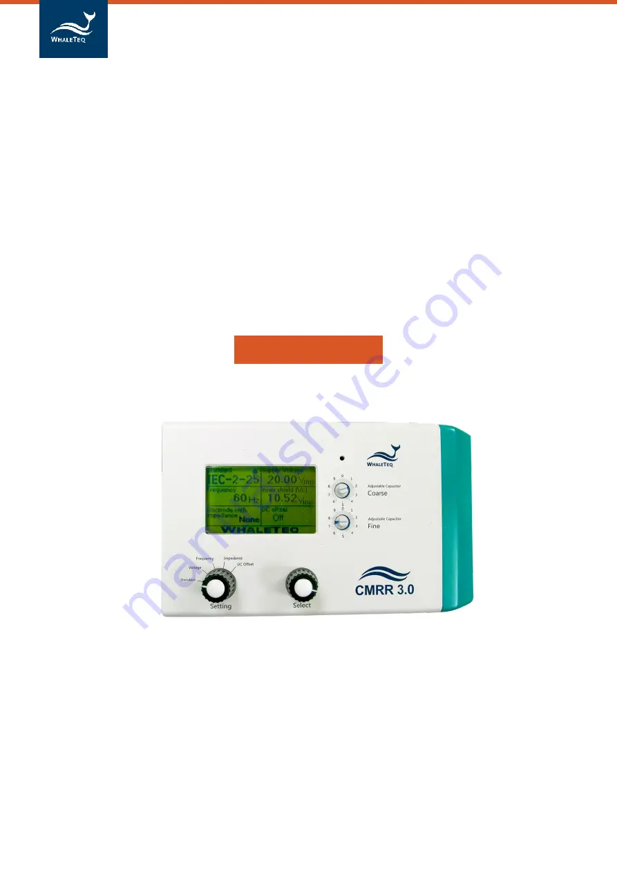
Common Mode Rejection Ratio Tester
(CMRR 3.0)
User Manual
(Revision 2017-10-06)
Страница 1: ...Common Mode Rejection Ratio Tester User manual WHALETEQ Common Mode Rejection Ratio Tester CMRR 3 0 User Manual Revision 2017 10 06 ...
Страница 2: ...his document and the programs as is without warranty of any kind either expressed or implied including but not limited to the implied warranties of merchantability or fitness for a particular purpose This document could contain technical inaccuracies or typographical errors Changes are periodically made to the information herein these changes will be incorporated in future revisions of this docume...
Страница 3: ... 11 5 1 2 Setting Knob 11 5 1 3 Select Knob 11 5 1 4 Coarse Knob 11 5 1 5 Fine Knob 11 5 1 6 70 71 Vrms Switch 11 5 2 Front Panel 12 5 2 1 Tapped Hole 12 5 2 2 USB Connector 12 5 2 3 DC 12V Terminal 12 5 2 4 Power Switch 12 5 2 5 Vc Terminal 12 5 2 6 Vs Terminal 13 5 2 7 Monitor Terminal 13 5 2 8 Grounding Terminal 13 5 3 Right Panel 13 5 3 1 CM Point Terminal 13 5 3 2 RA LA LL RL V1 V6 Electrode ...
Страница 4: ...Ratio Tester User manual 4 7 3 Vs voltage drop with the multimeter of 1MΩ input impedance 23 8 CMRR3 0 Specifications 23 9 Ordering Information 24 9 1 Package Contents 24 9 2 Optional Accessories 24 10 Contact Information 24 ...
Страница 5: ...ers 50 Hz 60 Hz 100 Hz and 120Hz Use coarse and fine knobs to adjust the variable capacitance value Ct The sum of Ct and Cx stray capacitance shall be 100pF Built in voltage measuring circuit for Vs and Vc voltages Vs value indicates the signal voltage generated by built in sine wave generator and Vc value is the voltage behind 100 pF capacitive voltage divider User can easily confirm whether Vc v...
Страница 6: ...agram of CMRR 3 0 Ct is the adjustable variable capacitance and Cx is the stray capacitance between inner shield and outer shield Figure 2 1 CMRR3 0 Electrical Diagram Item 1 Signal generator 2 Internal connection wires 2A Electrode terminals 3 300 mV DC Power Source 4 Inner Shield 5 Outer Shield 6 Isolated control circuit electrode 6A isolated control circuit signal generator 7 Voltage monitor Vs...
Страница 7: ...st environment per figure 3 1 turn on ECG DUT and adjust the sensitivity level to 10 mm mV After that turn off line frequency notch filter of ECG DUT and adjust Supply Voltage of CMRR 3 0 to off Make sure ECG noise level is below 1mm 0 1 mVpp 3 2 Shielding Case of ECG Holter If the noise is still high when testing ECG Holter in accordance with section 3 1 refer to figure 3 2 showing the connection...
Страница 8: ... the foil paper portion of patient cables to CM Point of CMRR 3 0 and connect the foil paper portion of ECG DUT to the reference outer shielding which refer to any screw holes of the shielding case 4 Fasten the upper cover of shielding case 5 Connect patient cables to the terminals of CMRR 3 0 and fasten the side metal holders of shielding case with CMRR 3 0 per shown in Fig 3 3 Fig 3 3 CMRR 3 0 w...
Страница 9: ...z and can have a much higher impedance imbalance The test in the standard simulates 10Vrms with an imbalance of 51kΩ 47nF and allows an indication equivalent to 0 35mVrms 1mVpp This requires ECG equipment to have a relatively large CMRR of 89dB1 In practice ECG equipment handles this large CMRR in five ways Intentional capacitance between the patient circuit and earth small enough not to cause lea...
Страница 10: ...7 1Vrms 20Vpp To resolve this problem a sine wave signal generator is built in CMRR3 0 It offers test voltages and frequencies required by various standards including 20 Vrms 2 828 Vrms 0 5 Vrms and 2 Vrms required by EEG IEC60601 2 26 test After resolving the drawbacks of external signal generator and insufficient supply voltage the test setup becomes easy and time saving Common mode rejection is...
Страница 11: ...or each main function For example when the main function is Voltage available parameters are 20 2 828 0 5 2 0 70 71 Vrms 5 1 4 Coarse Knob Located at the right side of the LSD display it is used to tune adjustable capacitance Ct to make its sum with stray capacitance Cx into 100pF The coarse scale ranges by tens of pF and the fine scale ranges by pFs 5 1 5 Fine Knob Located at the right side of th...
Страница 12: ...s USB connection and calibration 5 2 1 Tapped Hole The front and back panels each has two tapped holes for locking the outer metal shield which is a CMRR3 0 optional accessory 5 2 2 USB Connector Once connected to a PC CMRR3 0 operation can be commanded by the PC or controlled via the CRMRR3 0 assistant software 5 2 3 DC 12V Terminal It connects the DC 12V power supply bundled with CMRR3 0 to prov...
Страница 13: ...at connects the metal sheet in figure 3 1 in tests to reduce noises 5 3 Right Panel The right panel of CMRR3 0 is shown in figure 5 3 It is mainly used to connect each electrodes of ECG Figure 5 3 the right panel of CMRR3 0 5 3 1 CM Point Terminal Same as Vc terminal it connects the inner common mode point also referred to driven shield layer or inner shield of CMRR3 0 to this terminal When the pa...
Страница 14: ...it their chosen range in accordance with the requirements of each standard For example when IEC 2 25 is chosen Supply Voltage is limited to 20 Vrms and the frequency can only be 50 Hz or 60 Hz Figure 6 1 Options in Standard 6 1 1 2 Supply Voltage and Frequency Choose Manual for Standard option and turn Setting knob to Voltage Now the Select knob can choose Off 20 2 828 0 5 and 2 0 Vrms 200 56 6 8 ...
Страница 15: ... for Setting knob Now Select knob can choose whether to add 51KΩ 47nF parallel circuit to the test electrode Electrode with without Impedance Adding 51KΩ 47nF to all or none of the electrodes is referred to balanced test Adding 51KΩ 47nF to one of the electrodes or all the electrodes except one with the others in the opposite is referred to imbalanced test Available settings for CMRR3 0 are as fol...
Страница 16: ...t in total RA LA LL V1 As per the circuit diagrams in related standards 300 mV can be added only to RA for imbalanced and DC offset testing Figure 6 5 options in DC Offset CMRR 3 0 uses a built in battery supplying the electricity required by DC offset option Before turning off the power user must check and confirm DC offset is switched to OFF If not it would keep consuming battery power in the po...
Страница 17: ...for at least 15 seconds 6 1 2 2 IEC60601 2 47 2012 IEC 60601 2 47 is the testing standard for Holter monitor User can use CMRR 3 0 and follow the below testing procedures based on IEC 60601 2 47 to conduct the test 1 Set up a noise free test environment as per figure 3 1 2 Disconnect patient cables 3 Setting CMRR3 0 Standard to IEC 2 47 4 Select Supply Voltage to 2 828 Vrms and Frequency to 60 Hz ...
Страница 18: ...eed balanced and imbalanced tests with DC offset options This is to ensure the absolute balance of CMRR 3 0 output signals and increase the precision of CMRR test The following test procedures are all followed the requirements stated in IEC60601 2 26 and can be taken as test examples of CMRR 3 0 Due to the different naming rules between EEG and ECG standards hereby we use Ch1 Ch2 etc to prevent fr...
Страница 19: ...3 0 is connected to PC through USB interface CMRR 3 0 software will show the serial number in the title bar as shown in figure 6 6 The connection is successful if the serial number shows otherwise the message Device Not Found will appear The parameters can be set once the connection is successful The setting method is the same as unit operation After setting click Set button to send the set parame...
Страница 20: ...ut in one option because their test steps are completely the same Other standards with same steps are YY1079 1139 and EC 11 13 6 2 2 1 Step 1 Preparation First after clicking IEC 2 25 27 the test step automatically starts at Step 1 Preparation It also explains required settings as shown in the three green shaded descriptions in figure 6 7 1 No ECG patient cable is attached 2 The line frequency not...
Страница 21: ... tuned after detaching patient cable 6 2 2 4 Test Parameter Setting Set the test electrodes first not all the ECG models are having 12 leads In figure 6 9 all the electrodes are selected to meet the requirements of IEC60601 2 25 and IEC60601 2 27 Then choose Manual of Automatic test If manual test is chosen and Test Sequence is opened the right window in figure 6 9 will appear after clicking Run b...
Страница 22: ...01 2 25 2011 as the example Figure 6 10 IEC 2 25 27 test sequence window 7 Caution 7 1 Baseline noise test When the CMMR 3 0 is connected to the power supply it is impossible to eliminate high frequency noise from switching power supplies Such high frequency noise is unlikely to affect the test However in case of doubt the operator can select the NOISE setting turn the unit off and remove the powe...
Страница 23: ...input multimeter ex Fluke 87V to minimize the voltage drop range 8 CMRR3 0 Specifications Item Option Spec Supply voltage 0 5 2 828 20 2 70 71 Vrms 1 1 CM point voltage 1 414 10 1 35 355 Vrms 1 0 25Vrms 2 Frequency 50 60 100 120 Hz 1 Electrode with Impedance Using knob to change electrode None RA LA LL V1 V6 ALL Electrode without Impedance Using knob to change electrode RA LA LL V1 V6 Imbalance im...
Страница 24: ...V Power Supply Adapter excluding power cord 9 2 Optional Accessories CMRR Assistant Software IEC60601 2 25 27 47 CMRR Assistant Software IEC60601 2 26 CMRR Assistant Software YY0782 0885 1079 1139 AAMI ANSI EC11 13 External Shielding Case 10 Contact Information WHALETEQ Co LTD service whaleteq com O 886 2 2550 1239 9F 1 No 104 Minquan W Rd Taipei City 10361 Taiwan ...