LEONARDO PRO X
User manual
EN
10
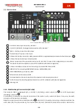
2.2. Connections
Pic.5 - Leonardo PRO X connection panel
AC-IN: AC mains input connection, 3x13mm
2
AC-OUT-1 (EPS OUT): Privileged load connection (EPS), 3x13mm
2
BAT+/- : Battery connections, M8 screws
Current Sense: TA sensor, 3.5mm jack
VE-Bus: Internal bus connection, RJ45 (Leonardo PRO X is supplied already connected to the VE-Bus port
VE-Bus: Internal control bus connection, RJ45
Meter: Connection of the production meter bus P1, 2x2.5mm
2
(in case of AC configuration) or connection
for maximum self-consumption (in case of DC installation with external regulators)
VE-Bus: Control Bus Connection for connecting a Leonardo PRO X Slave, RJ45
WBUS: Port for connecting WESTERN CO devices. (WRM, WBM), RJ11
CAN: CANBUS battery connection, RJ10
Ethernet: Internet connection, RJ45
Terminal block for internal connection of the maximum self-consumption contact
Contact output for activating auxiliary loads (in case of DC installation with external regulators)
Warning LED
2.2.1. Distribution grid connection (AC side)
The Leonardo PRO X is equipped with an AC-OUT-1 alternating current output and
an AC-IN input/output
alternating current line
.
3 connections are required for each grid connection of the inverter: earth, neutral and phase. In any case, the earth
connection of the inverter is mandatory.
Make the connection with the terminal block AC-IN
and AC-OUT-1 (if used) by connecting on the terminal block: the
earth cable (PE), the phase cable (L), the neutral cable (N). Each individual terminal block accepts a cable with a
1
1
2
6
2
1
3
8
7
9
10
11
4
5
6
12
13
14
13
12
14
1
2
3
4
5
6
7
8
9
10
11

