


Section DSA-WM2-140-202
030-101674 Rev. A
R
11
0803I2RA
Slot
#
Lead
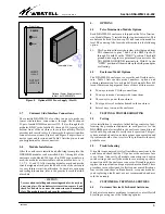
D
i ti
56-Pin DNI
C
t
Interface Card
Wirewrap Connector
Amphenol Connect-
ors, List S Colors
Slot
#
Lead
D
i ti
56-Pin DNI
C
t
Interface Card
Wirewrap Connector
Amphenol
Connectors
#
Description Connector
Pin #
Connector
Label/Position
Pin
#
XMT
Cable/
Connector
RCV
Cable/
Connector
#
Description Connector
Pin #
Connector
Label/Position
Pin
#
XMT
Cable/
Connector
RCV
Cable/
Connector
1
R1
47
POS 1
3
BL / W
8
R1
47
POS 8
3
G / R
T1
41
4
W / BL
T1
41
4
R / G
SGND
1
SGND
1
NC
2
NC
2
R
13
5
BL / W
R
13
5
G / R
T
7
6
W / BL
T
7
6
R / G
2
R1
47
POS 2
3
O / W
9
R1
47
POS 9
3
BR / R
T1
41
4
W / O
T1
41
4
R / BR
SGND
1
SGND
1
NC
2
NC
2
R
13
5
O / W
R
13
5
BR / R
T
7
6
W / O
T
7
6
R / BR
3
R1
47
POS 3
3
G / W
10
R1
47
POS 10
3
S / R
T1
41
4
W / G
T1
41
4
R / S
SGND
1
SGND
1
NC
2
NC
2
R
13
5
G / W
R
13
5
S / R
T
7
6
W / G
T
7
6
R / S
4
R1
47
POS 4
3
BR / W
11
R1
47
POS 11
3
BL / BK
T1
41
4
W / BR
T1
41
4
BK / BL
SGND
1
SGND
1
NC
2
NC
2
R
13
5
BR / W
R
13
5
BL / BK
T
7
6
W / BR
T
7
6
BK / BL
5
R1
47
POS 5
3
S / W
12
R1
47
POS 12
3
O / BK
T1
41
4
W / S
T1
41
4
BK / O
SGND
1
SGND
1
NC
2
NC
2
R
13
5
S / W
R
13
5
O / BK
T
7
6
W / S
T
7
6
BK / O
6
R1
47
POS 6
3
BL / R
13
R1
47
POS 13
3
G / BK
T1
41
4
R / BL
T1
41
4
BK / G
SGND
1
SGND
1
NC
2
NC
2
R
13
5
BL / R
R
13
5
G / BK
T
7
6
R / BL
T
7
6
BK / G
7
R1
47
POS 7
3
O / R
14
R1
47
POS 14
3
BR / BK
T1
41
4
R / O
T1
41
4
BK / BR
SGND
1
SGND
1
NC
2
NC
2
R
13
5
O / R
R
13
5
BR / BK
T
7
6
R / O
T
7
6
BK / BR
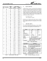
Table 2. Network Interface Connections


