Hopkinsons Fig 9052VALVE ACTUATOR
Standard Operating & Maintenance Instructions
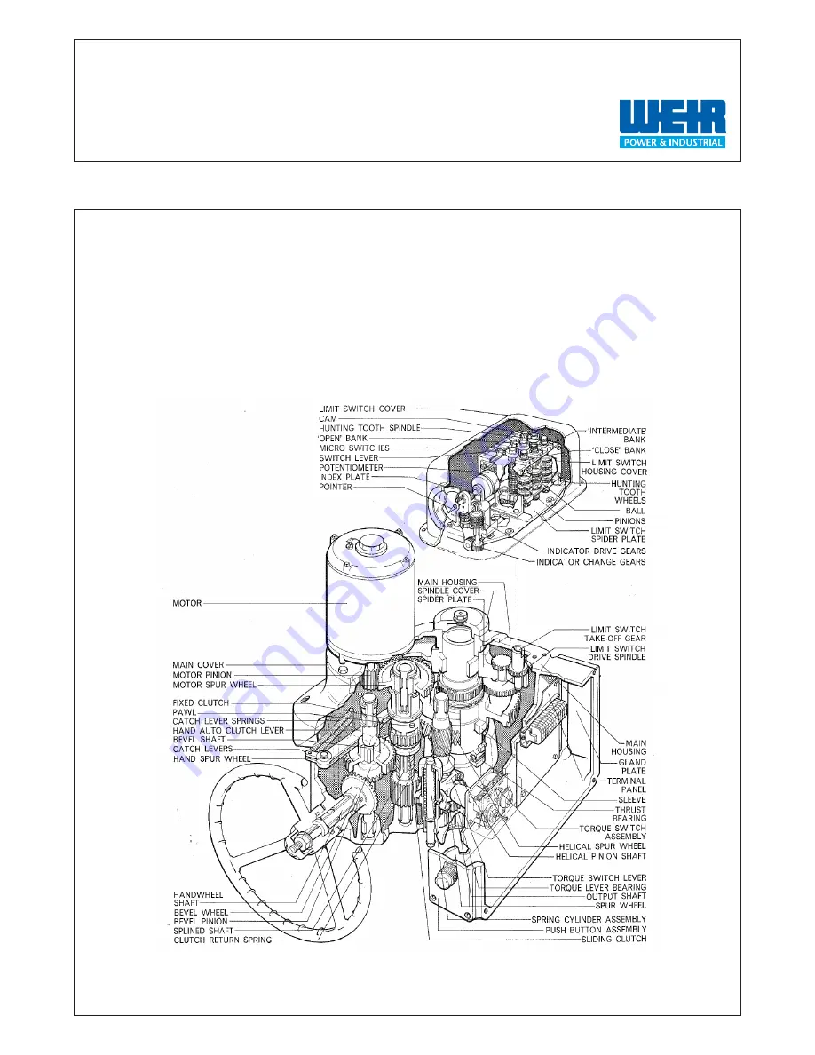
CUT-AWAY OF FIG. 9052 GEAR BOX, WITH LIMIT SWITCH
& VALVE POSITION INDICATOR
ExcellentPower & IndustrialSolutions
HOP 9052 /Jan 2011
Страница 1: ...pkinsons Fig 9052 VALVE ACTUATOR Standard Operating Maintenance Instructions CUT AWAY OF FIG 9052 GEAR BOX WITH LIMIT SWITCH VALVE POSITION INDICATOR Excellent Power Industrial Solutions HOP 9052 Jan 2011 ...
Страница 2: ...issioning Direct Mounted Actuators Page 7 2 4 Mechanical Valve Position Indicator When Fitted Page 8 2 5 Motor Page 8 2 6 Alternating Current Page 8 2 7 Lubrication Page 8 Drawings Arrangement of Fig 9052 Actuator Page 10 Sectional Arrangement of Gear Box Assembly for Fig 0052 Actuator Page 11 Cut Away of Fig 9052 Gear Box With Limit Switch Valve Position Indicator Page 12 Arrangement of Fig 9052 ...
Страница 3: ...corporates a lost motion or hammer blow device which allows the motor to run up to speed before transmitting full torque to the valve 1 3 TORQUE LIMITING DEVICE The final reduction stage in the actuator drive consists of a single helical spur pinion shaft which is capable of axial movement against a spring Upon a predetermined torque being exceeded the end thrust component causes axial movement of...
Страница 4: ...of the sliding clutch member to engage with the hand spur wheel Do not attempt to force the lever into the manual position as this should be easily and smoothly attained With the lever in the manual position the motor pinion and motor gear are bypassed for hand operation By this action the catch levers which are clear of the fixed clutch member pawls during power operation are allowed to make cont...
Страница 5: ...drive of the hunting tooth gear and spur wheel is locked in position by the spindle Resetting of a switch bank is effected by pulling out the hunting tooth spindle to allow the spring loaded ball in the housing to register the disengaged position and also to bring the grooves in the spindle in line with the drive ball of each hunting tooth wheel With the spindle in the disengaged position the hunt...
Страница 6: ... spindles An adjusting screw permits the adjusting plate to be set in any of 12 positions from 0 5 to 1 1 50 110 output torque by simply releasing the adjusting screw sufficiently to allow the teeth of the adjusting plate to clear the teeth of the index plate rotating the adjusting plate to the required figure and tightening the adjusting screw The driving dog tooth of the adjusting plate is there...
Страница 7: ...te number in a straight line in line with the pinion and hunting tooth spindles Withdraw the hunting tooth spindle of the close bank and re set to 0000 turns in line and re engage the spindle Now set the intermediate and open banks to the correct number of actuator output shaft turns from zero at which these switches are required to trip Check by hand operation the tripping positions of the switch...
Страница 8: ...lve with the movement of the controller by having the valve in mid position Then press the open or shut operating button and immediately after that stop the actuator and ascertain whether the valve has moved to correspond to the button which was operated If the valve has travelled in the opposite direction reverse any two of the supply leads in the contactor 2 7 LUBRICATION The actuator requires t...
Страница 9: ... Industrial First choice for power and industrial protection ROCOL MOLYGEAR Internal power and hand gears prelubricated at works sufficient for normal life of actuator Dependent upon usage and operating conditions ...
Страница 10: ...10 Weir Power Industrial First choice for power and industrial protection ARRANGEMENT OF FIG 9052 ACTUATOR ...
Страница 11: ...11 Weir Power Industrial First choice for power and industrial protection SECTIONAL ARRANGEMENT OF GEAR BOX ASSEMBLY FOR FIG 9052 ACTUATOR ...
Страница 12: ...12 Weir Power Industrial First choice for power and industrial protection CUT AWAY OF FIG 9052 GEAR BOX WITH LIMIT SWITCH VALVE POSITION INDICATOR ...
Страница 13: ...13 Weir Power Industrial First choice for power and industrial protection ARRANGEMENT OF FIG 9052 ACTUATOR PEDESTAL MOUNTED ...
Страница 14: ...14 Weir Power Industrial First choice for power and industrial protection ARRANGEMENT OF LIMIT SWITCH SUITABLE FOR FIG 9051 9052 9053 9054 9055 9056 ACTUATORS ...
Страница 15: ...15 Weir Power Industrial First choice for power and industrial protection DIAGRAMMATIC CUT AWAY OF LIMIT SWITCH ASSEMBLY ...
Страница 16: ...16 Weir Power Industrial First choice for power and industrial protection ARRANGEMENT OF TORQUE SWITCH ...
Страница 17: ... 905 625 7202 Servicecall 877 797 WEIR 9347 Fax 1 905 766 4048 E mail valveservices weirgroup com Web www weirpowerindustrial com Excellent Power Industrial Solutions Rest of World Weir Power and Industrial The Harlands Alloa FK10 1TB United Kingdom Telephone 44 0 1259 727550 Fax 44 0 1259 727570 E mail sales coordinator weirgroup com Web www weirpowerindustrial com www weirpowerindustrial com ...