6 Commissioning
| Commissioning with Studio 5000 (Ethernet/IP)
30
2547720000/03/09.2019
Manual Communication module UR20-4COM-IO-LINK
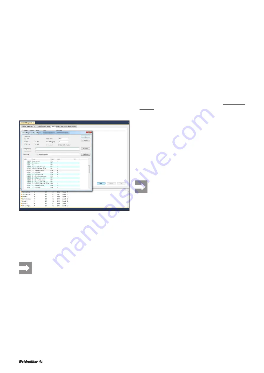
Integrating IO-Link device with TwinCAT
An IO-Link device is integrated using the appropriate parame-
terisation of the associated IO-Link port.
▶
Switch to
Startup
.
The current parameter setting is displayed.
You can edit the parameter setting.
▶
Double-click the parameter you want to edit.
The
Edit
dialogue box is opened.
Editing module parameters with TwinCAT
▶
Set the “Operating mode” parameter of the IO-Link port to
the value “IO-Link” (0x03).
▶
Set the “Process data length input” parameter to the
value “auto (default)” (0x21).
▶
Set the “Process data length output” parameter to the
value “auto (default)” (0x21).
▶
Change the other parameters as required.
All settings only take effect once they have been
loaded into the component.
6.7 Commissioning with Studio 5000
(Ethernet/IP)
Installing the device description files
▶
Start Studio 5000.
▶
Download and unzip the archive file from the Weidmüller
▶
In the
Tools
menu within the Studio 5000 software,
select the
EDS Hardware Installation Tool
option.
▶
Follow the installation wizard.
Integrating IO-Link master with Studio 5000
▶
Start Studio 5000.
▶
Create a new project or open an existing project.
▶
Configure the control unit and the network as usual.
▶
Establish a connection to the controller (
Go Online
).
If your project does not match the project on the controller,
load your project onto the controller (
Download
) or transfer
the project from the controller to Studio 5000 (
Upload
). The
controller must be in programming mode in both cases.
All projects downloaded from Studio 5000 to the
controller irrevocably overwrite any projects saved
on the controller.
▶
Add the u-remote station as usual.
The fieldbus coupler and module are added with the stand
-
ard process data width. Usually, this process data width does
not correspond with the existing IO-Link device configura
-
tion.
You can adjust the process data length of the module to
your IO-Link device configuration using a sequence of acyclic
write operations. The following descriptions are examples of
the procedure with RSNetworx for EtherNet/IP. Alternatively,
you can implement the write operations with the MSG func-
tion component as generic CIP messages.
▶
Switch to RUN mode.
▶
Start RSNetworx for EtherNet/IP.
▶
Scan the network.
▶
Right-click the fieldbus coupler.
▶
In the context menu, click
Class Instance Editor
.
▶
Read the warning message and confirm by clicking on
Yes
.
The
Class Instance Editor
is opened.
Содержание UR20 Series
Страница 1: ...Remote I O System u remote UR20 Communication module UR20 4COM IO LINK Manual Let s connect...
Страница 8: ...8 2547720000 03 09 2019 Manual Communication module UR20 4COM IO LINK...
Страница 10: ...10 2547720000 03 09 2019 Manual Communication module UR20 4COM IO LINK...
Страница 20: ...20 2547720000 03 09 2019 Manual Communication module UR20 4COM IO LINK...
Страница 48: ...48 2547720000 03 09 2019 Manual Communication module UR20 4COM IO LINK...
Страница 54: ...54 2547720000 03 09 2019 Manual Communication module UR20 4COM IO LINK...


