background image

14

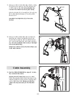
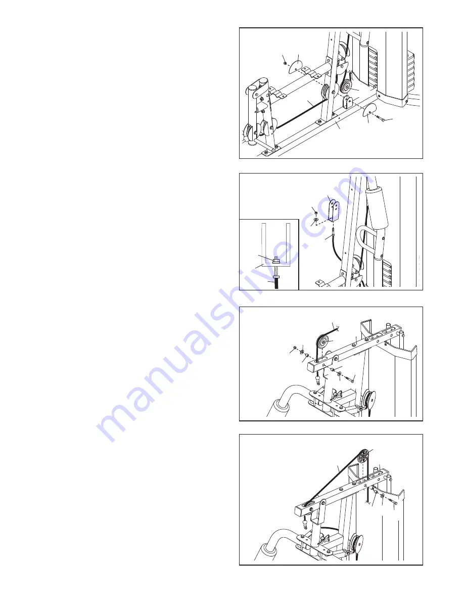
22. Route the Low Cable (53) under a 90mm Pulley

(48). Attach the Pulley and two Half Guards (43)

to the Base (1) with an M10 x 46mm Bolt (81)

and an M10 Locknut (56).

Make sure that the

Half Guards are on the outside of the bracket

as shown.

53

43

1

43

81

56

48

22

23. Attach the Low Cable (53) to the U-bracket (45)

with an M8 Washer (59) and an M8 Locknut (58).

See the inset drawing. Do not overtighten the

Locknut; it should be threaded onto the end

of the Cable so that only two threads are

showing above the Locknut.

53

45

58

58

45

59

53

23

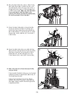
24.

Identify the High Cable (55).

Route the Cable up

through the Top Frame (4) and over a 90mm

Pulley (48). Attach the Pulley inside the Top

Frame with an M10 x 67mm Bolt (71), two M10

Washers (57), two 12mm Spacers (52), and an

M10 Locknut (56).

25. Route the High Cable (55) over a 90mm Thin

Pulley (47) and down through the Top Frame (4).

Attach the Thin Pulley inside the Top Frame with

an M10 x 67mm Bolt (71), an M10 Washer (57),

and an 11mm Spacer (49).

Make sure that the

Thin Pulley does not fall out of the Top Frame

while you complete steps 26 and 27.

4

55

49 57

47

71

25

56

4

55

52

52

57

57

48

71

24

Содержание 8980 I

Страница 1: ...manual for future reference Model No WEANSY1978 0 Serial No Write the serial number in the space above for reference USERʼS MANUAL QUESTIONS If you have questions or if there are missing or damaged parts please contact the establish ment where you purchased this product Serial Number Decal under seat ...

Страница 2: ...ES 23 PART LIST 25 EXPLODED DRAWING 26 ORDERING REPLACEMENT PARTS Back Cover WARNING DECAL PLACEMENT Keep hands and fingers clear of this area This decal is placed on both sides of the upright and on the pivot frame This drawing shows the location s of the warning decal s If a decal is missing or illegible see the front cover of this manual and request a free replace ment decal Apply the decal in ...

Страница 3: ...o tection 9 Keep hands and feet away from moving parts 10 Always secure the weight stack with the lock pin and lock after exercising to prevent unauthorized use of the weight system see LOCKING THE WEIGHT STACK on page 20 11 Make sure that the cables remain on the pul leys at all times If the cables bind as you are exercising stop immediately and make sure that the cables are on the pulleys 12 Alw...

Страница 4: ...oal is to tone your body build dramatic muscle size and strength or improve your cardiovascular system the weight system will help you to achieve the specific results you want For your benefit read this manual carefully before using the treadmill If you have questions after read ing this manual please see the front cover of this man ual To help us assist you note the product model number and seria...

Страница 5: ... x 20mm Self tapping Screw 69 M10 x 77mm Bolt 79 M10 x 51mm Bolt 66 M10 Washer 57 M5 x 20mm Self tapping Screw 64 M12 Nut 84 Large Washer 85 M8 x 63mm Carriage Bolt 87 Refer to the drawings below to identify small parts used in assembly The number in parentheses by each draw ing is the key number of the part from the PART LIST near the end of this manual Note Some small parts may have been preatta...

Страница 6: ...ve divided the assembly process into four stages The parts needed for each stage are found in individual hardware kits Place all parts in a cleared area and remove the packing materials Do not dispose of the packing materials until assembly is completed For help identifying small parts use the PART IDENTIFICATION CHART on page 5 As you assemble the weight system make sure all parts are oriented as...

Страница 7: ...Locknuts Attach the Upright 3 to the Base 1 with the two indicated M8 x 63mm Carriage Bolts 87 and two M8 Locknuts 58 Do not tighten the Locknuts yet 1 Insert four M8 x 63mm Carriage Bolts 87 up through the Base 1 Note It may be helpful to place a piece of tape over the bolt heads to hold them in place Before beginning assembly make sure you understand the information on page 6 Frame Assembly 87 5...

Страница 8: ...ttach the Seat Frame 6 to the Front Leg 7 in the same manner 5 Slide the two Weight Bumpers 27 onto the Weight Guides 21 Orient the six Weights 22 with the pin holes on the bottom as shown Slide the Weights onto the Weight Guides Insert the Weight Selector Cap 23 into the Weight Selector 24 Insert the Weight Selector into the six Weights 22 Make sure that the pin on the Weight Selector is oriented...

Страница 9: ...2 78 82 17 20 19 64 72 72 6 Orient the Top Frame 4 with the welded support on the bottom Attach the Top Frame 4 to the Upright 3 with two M8 x 65mm Bolts 68 two M8 Washers 59 and two M8 Locknuts 58 Do not tighten the Locknuts yet Attach the Top Frame 4 between the Weight Guides 21 with an M10 x 155mm Bolt 74 two M10 Washers 57 two 19mm Spacers 76 and an M10 Locknut 56 See steps 2 4 and 6 Tighten t...

Страница 10: ...on the side shown Attach the Leg Lever to the Front Leg 7 with the Bolt and an M10 Locknut 56 Do not overtighten the Locknut the Leg Lever must pivot easily 10 Grease an M10 x 77mm Bolt 79 Attach the Pivot Frame 5 to the Top Frame 4 with the Bolt and an M10 Locknut 56 Do not overtighten the Locknut the Pivot Frame must pivot easi ly Attach the two Arm Pins 40 to the Pivot Frame 5 with two M4 x 20m...

Страница 11: ...54 Grease an M8 x 22mm Shoulder Bolt 65 Attach the Cable to the indicated Cable Pivot 39 with the Shoulder Bolt and an M8 Locknut 58 Make sure that the cable end can pivot easily on the Shoulder Bolt 12 Grease an M10 x 85mm Bolt 67 and two Arm Bushings 44 Attach the Right Arm 9 to the Pivot Frame 5 with the Bolt two M10 Washers 57 the two Arm Bushings and an M10 Locknut 56 Do not overtighten the L...

Страница 12: ... M10 Locknut 56 Make sure that the Cable Trap is oriented to hold the Cable in the groove of the V pulley 15 Route the Arm Cable 54 under a 90mm Pulley 48 Attach the Pulley and two Half Guards 43 to the Double U bracket 63 with an M10 x 46mm Bolt 81 and an M10 Locknut 56 Make sure that the Half Guards are on the outside of the U bracket as shown 56 3 57 46 50 41 75 54 41 48 43 43 63 81 56 54 56 3 ...

Страница 13: ...ers 52 and an M10 Locknut 56 56 7 53 52 52 57 57 48 71 19 8 7 53 52 52 57 57 48 71 56 18 20 Route the Low Cable 53 under a 90mm Pulley 48 and through the Upright 3 Attach the Pulley inside the Upright with an M10 x 67mm Bolt 71 two M10 Washers 57 two 12mm Spacers 52 and an M10 Locknut 56 56 3 53 52 52 57 57 48 71 20 21 Route the Low Cable 53 over a 90mm Pulley 48 Attach the Pulley and two Half Gua...

Страница 14: ...that only two threads are showing above the Locknut 53 45 58 58 45 59 53 23 24 Identify the High Cable 55 Route the Cable up through the Top Frame 4 and over a 90mm Pulley 48 Attach the Pulley inside the Top Frame with an M10 x 67mm Bolt 71 two M10 Washers 57 two 12mm Spacers 52 and an M10 Locknut 56 25 Route the High Cable 55 over a 90mm Thin Pulley 47 and down through the Top Frame 4 Attach the ...

Страница 15: ...an M10 x 67mm Bolt 71 two M10 Washers 57 two 12mm Spacers 52 and an M10 Locknut 56 71 55 52 52 48 57 4 57 56 28 27 Route the High Cable 55 up through the Top Frame 4 and over a 90mm Thin Pulley 47 Attach the Pulley inside the Top Frame with the M10 x 67mm Bolt 71 used in step 25 an 11mm Spacer 49 an M10 Washer 57 and an M10 Locknut 56 55 47 71 4 49 57 56 27 29 Note The shroud is shown removed in t...

Страница 16: ... 32 Attach the Lock Plate 73 to the Front Leg 7 with an M10 x 70mm Bolt 86 an M10 Washer 57 and an M10 Locknut 56 Do not overtight en the Locknut the Lock Plate must pivot easily Attach the Leg Lever Pin 38 to the Front Leg 7 with an M4 x 20mm Self tapping Screw 69 Insert the Leg Lever Pin through the Leg Lever 8 and the Lock Plate 73 70 70 82 82 3 15 62 6 56 57 69 38 86 8 73 7 32 31 16 30 ...

Страница 17: ...orrect the problem IMPORTANT If the cables are not properly installed they may be damaged when heavy weight is used See the CABLE DIAGRAM on page 21 for proper cable routing If there is any slack in the cables you will need to remove the slack by tightening the cables See MAINTENANCE on page 22 33 Insert the Pad Tube 29 into the Front Leg 7 Slide two Small Foam Pads 28 onto the ends of the Pad Tub...

Страница 18: ...wn Note Do not use the Top Weight 25 by itself Note Due to the cables and pulleys the amount of resistance at each exercise station may vary from the weight setting Use the WEIGHT RESISTANCE CHART on page 20 to find the approximate amount of resistance for each weight station ATTACHING THE ACCESSORIES TO A PULLEY STATION Attach the Lat Bar 35 to the High Cable 55 at the high pulley station with a ...

Страница 19: ... Curl Knob 61 Before performing an exercise that does not require the Curl Pad 14 remove the Curl Pad and press the 50mm Round Inner Cap 30 into the Front Leg 7 Store the Curl Pad away from the weight system 5 40 3 Holes 13 61 14 7 30 9 10 38 8 73 ARM CONVERSION To use the Arms 9 10 as butterfly arms insert the Arm Pins 40 into the holes in the Upright 3 and the Pivot Frame 5 as shown To use the A...

Страница 20: ...the 12 5 lb weights Note The weight resistance shown for the butterfly arm station is for each arm The actual resistance at each station may vary due to differences in individual weights as well as friction between the cables pulleys and weight guides Note 1 lb 0 45 kg WEIGHT Top 1 2 3 4 5 6 HIGH PULLEY lbs 11 26 42 61 70 86 101 BUTTERFLY ARM lbs 16 22 30 41 51 63 82 PRESS ARM lbs 27 44 62 97 127 ...

Страница 21: ...e traps and guards are assembled correctly If the cables are not assembled correctly the weight system will not function properly and damage may occur Make sure that the cable traps do not touch or bind the cables 1 2 4 2 3 4 5 5 Arm Cable 54 Length 7 ft 5 in 226 cm High Cable 55 Length 9 ft 6 in 290 cm Low Cable 53 Length 10 ft 8 in 325 cm 3 1 6 1 2 3 4 5 6 CABLE DIAGRAM ...

Страница 22: ...move the M10 Locknut 56 and the M10 x 51mm Bolt 66 from the Cable Trap 51 the 90mm Pulley 48 the two Half Guards 43 and the U bracket 45 Reattach the Pulley Cable Trap and Half Guards to the other hole in the U bracket Make sure that the Cable Trap is in the proper position and that the Low Cable 53 and Pulley move smooth ly Loosen the M12 Nut 84 on the High Cable 55 Tighten the Cable into the Wei...

Страница 23: ... Tuesday and Thursday Rest from both strength training and aerobic exercise for at least one full day each week to give your body time to regenerate The combination of strength training and aerobic exer cise will reshape and strengthen your body plus devel op your heart and lungs PERSONALIZING YOUR EXERCISE PROGRAM Determining the appropriate length of time for each workout and the numbers of repe...

Страница 24: ...nd inhale during the return stroke Never hold your breath Rest for a short period of time after each set The ideal resting periods are Rest for three minutes after each set for a muscle building workout Rest for one minute after each set for a toning work out Rest for 30 seconds after each set for a weight loss workout Plan to spend the first couple of weeks familiarizing yourself with the equipme...

Страница 25: ...ivot 40 2 Arm Pin 41 4 Full Guard 42 2 Large Foam Pad 43 8 Half Guard 44 4 Arm Bushings 45 1 U bracket 46 2 V pulley 47 2 90mm Thin Pulley 48 9 90mm Pulley 49 2 11mm Spacer 50 2 Large Cable Trap 51 1 Cable Trap 52 10 12mm Spacer 53 1 Low Cable 54 1 Arm Cable 55 1 High Cable 56 22 M10 Locknut 57 27 M10 Washer 58 13 M8 Locknut 59 7 M8 Washer 60 1 Leg Bumper 61 1 Curl Knob 62 12 M6 x 16mm Screw 63 1 ...

Страница 26: ...77 30 77 13 62 36 35 36 15 6 62 62 68 68 68 68 61 58 58 56 57 30 69 33 30 56 79 52 57 56 52 48 57 30 71 34 28 53 28 69 57 56 52 48 58 58 52 73 86 71 31 43 71 8 34 60 57 9 10 7 40 69 57 57 59 59 38 37 83 80 57 30 14 28 34 34 29 28 1 87 87 81 43 56 48 71 EXPLODED DRAWING A Model No WEANSY1978 0 R0608A 26 ...

Страница 27: ... 52 49 57 57 71 18 17 62 53 43 66 43 48 56 51 58 59 45 19 62 64 20 62 32 70 82 56 56 41 57 46 50 41 75 41 58 58 57 46 59 59 68 50 41 75 70 82 58 59 57 57 56 52 52 71 58 58 48 56 56 81 43 48 43 48 43 43 63 81 82 82 72 82 82 76 57 57 12 88 89 62 82 62 82 82 78 16 EXPLODED DRAWING B Model No WEANSY1978 0 R0608A 27 ...

Страница 28: ...elp us assist you be prepared to provide the following information when contacting us the model number and serial number of the product see the front cover of this manual the name of the product see the front cover of this manual the key number and description of the replacement part s see the PART LIST and the EXPLODED DRAWING near the end of this manual ...

Отзывы: