English
TECHNICAL SPECIFICATIONS
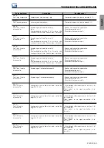
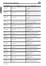
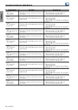
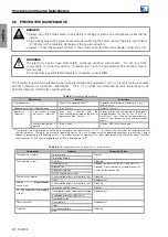
8 TECHNICAL SPECIFICATIONS
8.1 INVERTER POWER DATA
8.1.1
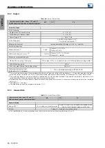
Input
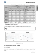
Table 8.1:
Inverter Input Data
Inverter smart code - items ”IV” and ”V”
Suffix number of phases and rated voltage
B2
T2
T4
AC Power Supply
Number of phases (input)
1 or 3
3
3
Rated input voltage
200 ... 240 Vrms
Frames A, B and C: 200...240 Vrms
Frames D and E: 208...240 Vrms
380...480 Vrms
Input voltage tolerance
-15% +10%
Frame A, B and C: -15%+10%
Frames D and E: -15% +10%
(1)
-15% +10%
Input frequency
50/60 Hz (range: 48 ... 63 Hz)
Phase unbalance
≤3% between line voltages
Overvoltages / transients
Category III (EN 61010 / IEC61800-5-1 / UL61800-5-1)
Input rated current
-Three-phase power supply
1.1 x Io,nom
Io,nom
Io,nom
-Single-phase power supply
2.06 x Io,nom
-
-
Inverter power factor for rated condition
ND
(2)
-Three-phase power supply
0.77
0.93
0.93
-Single-phase power supply
0.70
-
-
Inverter displacement factor (cos phi)
≥0.98
Harmonic distortion of the input current (THDi)
≤ 42% for 75 to 100% of Io,nom
(3)
Maximum number of powerups (network connections)
Maximum 1 per minute
Types of power supply
(4)
Frame Size A: TT / TN / IT (Except grounded by resistor) - slash voltage
Frame Sizes B, C, D, E: TT / TN / IT / Delta earthed - straight voltage
Efficiency (Efficiency class)
(5)
IE2 (IEC61800-9-2 / EN50598-2)
DC power supply
(6) (7)
Input voltage range
229....400 Vcc
Frames A, B and C: 229....400 Vdc
Frames D and E: 252...400 Vdc
436...800 Vdc
Input rated current
1.15x Io,nom
(1)
For input voltage in the range 208 ≤ Vin < 220 Vrms the negative tolerance is -10%.
(2)
For the inverter input THDi values, please contact WEG.
(3)
Typical value. Valid only for balanced power supplies.
(4)
For operation on IT networks or networks grounded by high impedance, follow the grounding guidelines of
(5)
Efficiency levels by model can be found in the ”WEG Ecodrive” app available for Android and iOS devices.
(6)
For DC power supply, an external pre-charge circuit must be used. Exception: in CFW900 inverters with frames A, B and C, it is possible to
connect the ”+” terminal of the DC power supply to the DC+ terminal and the ”-” terminal to the R/L1/L and S/L2/N terminals. In this case,
it is not necessary to use an external pre-charge.
(7)
For applications with common DC link, please consult WEG.
CFW900 | 95


