


Faults and Alarms
15
CFW700 | 15-3
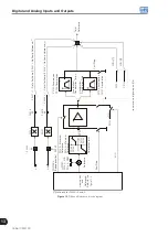
PTC
XC1:
22
23
28
27
AI1
AO1
CC700
Program P0231 = 4;
Set S1.4 = OFF (0 to 10 V).
Program P0251 = 11;
Set S1.1 = OFF (4 to 20 mA, 0 to 20 mA).
(a) AO1, AI1
Program P0236 = 4;
Set S1.3 = OFF (0 to 10 V).
Program P0254 = 11;
Set S1.2 = OFF (4 to 20 mA, 0 to 20 mA).
PTC
25
26
30
29
AI2
AO2
(b) AO2, AI2
Figure 15.1 (a) to (b):
PTC connection examples
15.3 PROTECTIONS
The parameters related to motor and inverter protections are found in this group.
P0030 – IGBTs Temperature
P0034 – Internal Air Temperature
Adjustable
Range:
-20.0 to 150.0 °C
Factory
Setting:
Properties:
ro
Access groups
via HMI:
READ
Description:
These parameters present, in Celsius degrees, the heatsink temperature (P0030) and also of the internal air
(P0034).
They are useful to monitor the temperature on the main inverter sections in case of an occasional inverter
overheating.
Содержание CFW700
Страница 2: ......
Страница 4: ......
Страница 8: ...Summary...
Страница 34: ...2 General Information 2 4 CFW700...
Страница 38: ...3 About the CFW700 3 4 CFW700...
Страница 56: ...7 Starting up and Settings 7 4 CFW700...
Страница 58: ...8 Available Control Types 8 2 CFW700...
Страница 78: ...10 VVW Control 10 8 CFW700...
Страница 158: ...13 Digital and Analog Inputs and Outputs 13 28 CFW700...
Страница 184: ...16 Read only Parameters 16 12 CFW700...