12
Functions Common to all the Control Modes
12-14 | CFW700
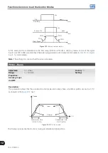
F021
t0 t1
t2
t3 t4 t5
t
U
d
Nominal
Return (P0323)
Loss (P0321)
Ride-Through (P0322)
Undervoltage (75 %)
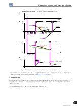
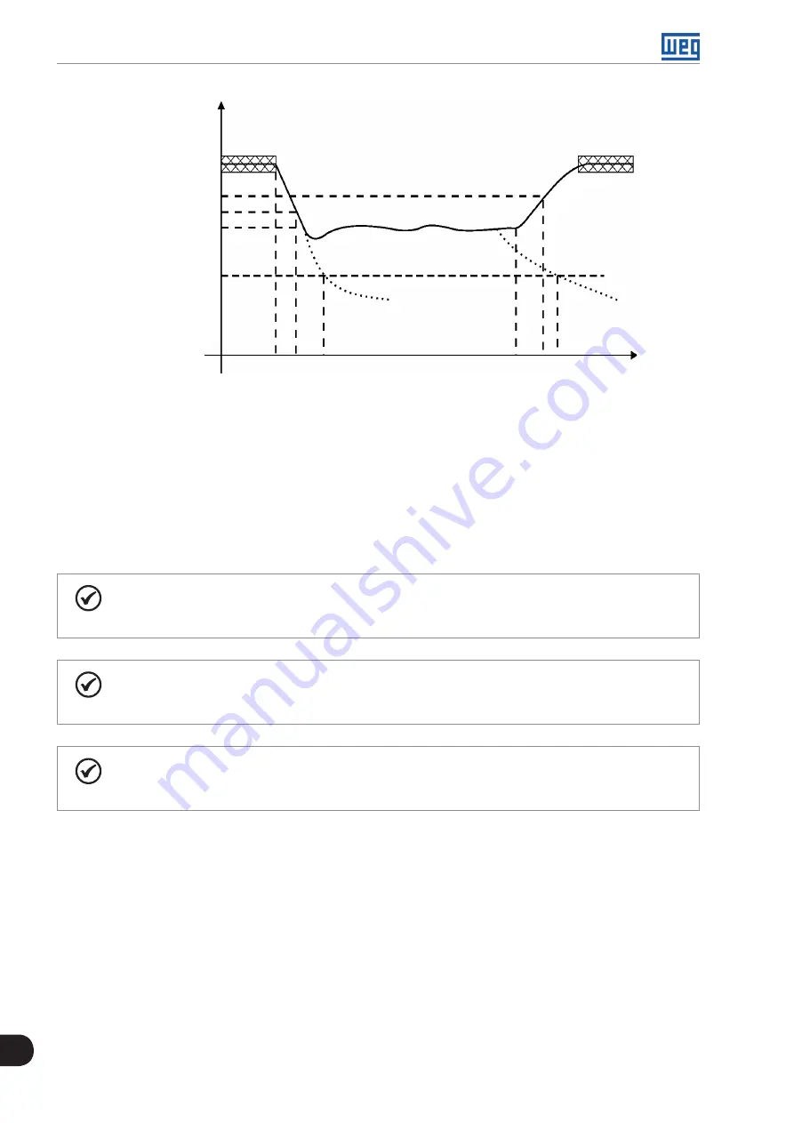
Figure 12.6:
Ride-Through function actuation in vector mode
t0 – Line loss.
t1 – Line loss detection.
t2 – Undervoltage actuation (F021 without Ride-Through).
t3 – Line return.
t4 – Line return detection.
t5 – Undervoltage actuation (F021 with Ride-Through).
If the line voltage produces an U
d
voltage between the values adjusted in P0322 and P0323, the fault F150 may
occur, the values of P0321, P0322 and P0323 must be readjusted.
NOTE!
When one of the functions, Ride-Through or Flying Start, is activated, the parameter P0357 (Line
Phase Loss Time) is ignored, regardless of the adjusted time.
NOTE!
Cautions with the application:
Use oversized high-speed fuses or regular fuses to limit the inrush current when the line returns.
NOTE!
The Ride-Through function activation occurs when the power supply voltage is lower than the value
(P0321/1.35). U
d
=Vac x 1.35
Содержание CFW700
Страница 2: ......
Страница 4: ......
Страница 8: ...Summary...
Страница 34: ...2 General Information 2 4 CFW700...
Страница 38: ...3 About the CFW700 3 4 CFW700...
Страница 56: ...7 Starting up and Settings 7 4 CFW700...
Страница 58: ...8 Available Control Types 8 2 CFW700...
Страница 78: ...10 VVW Control 10 8 CFW700...
Страница 158: ...13 Digital and Analog Inputs and Outputs 13 28 CFW700...
Страница 184: ...16 Read only Parameters 16 12 CFW700...

