
Functions Common to all the Control Modes
12
CFW700 | 12-1
12 FUNCTIONS COMMON TO ALL THE CONTROL MODES
This section describes the functions that are common to all the CFW700 inverter control modes (V/f, VVW,
Sensorless, and Encoder).
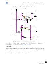
12.1 RAMPS
The inverter RAMPS functions allow the motor to accelerate and decelerate in a faster or a slower manner.
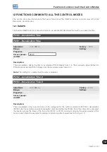
P0100 – Acceleration Time
P0101 – Deceleration Time
Adjustable
Range:
0.0 to 999.0 s
Factory
Setting:
20.0 s
Properties:
Access groups
via HMI:
BASIC
Description:
These parameters define the time to accelerate (P0100) lineally from 0 to the maximum speed (defined in
P0134) and decelerate (P0101) lineally from the maximum speed down to 0.
Note:
The setting 0.0 s means that the ramp is disabled.
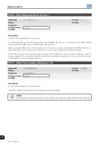
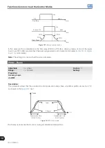
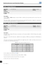
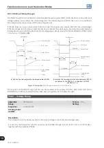
P0102 – Acceleration Time 2
P0103 – Deceleration Time 2
Adjustable
Range:
0.0 to 999.0 s
Factory
Setting:
20.0 s
Properties:
Access groups
via HMI:
Description:
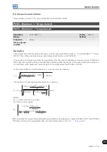
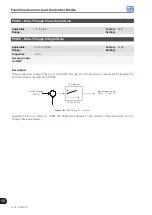
Those parameters allow a second ramp to be configured for the motor acceleration (P0102) or deceleration
(P0103), which is activated via an external digital command (defined by P0105). Once this command is activated,
the inverter ignores the times of the first ramp (P0100 or P0101) and starts obeying the value adjusted at the
second ramp. Refer the example for external command via DIx showed next in the
.
Содержание CFW700
Страница 2: ......
Страница 4: ......
Страница 8: ...Summary...
Страница 34: ...2 General Information 2 4 CFW700...
Страница 38: ...3 About the CFW700 3 4 CFW700...
Страница 56: ...7 Starting up and Settings 7 4 CFW700...
Страница 58: ...8 Available Control Types 8 2 CFW700...
Страница 78: ...10 VVW Control 10 8 CFW700...
Страница 158: ...13 Digital and Analog Inputs and Outputs 13 28 CFW700...
Страница 184: ...16 Read only Parameters 16 12 CFW700...