


Functions Common to All the Control Modes
CFW500 | 11-3
11
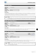
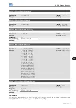
P0105 – 1
st
/ 2
nd
Ramp Selection
Adjustable
Range:
0 = 1
st
Ramp
1 = 2
nd
Ramp
2 = DIx
3 = Serial/USB
4 = Reserved
5 = CO/DN/DP
6 = SoftPLC
Factory
Setting:
2
Properties:
Access Groups
via HMI:
I/O
Description:
It defines the command origin source to activate the 2
nd
Ramp.
Note: Parameter P0680 (Logical Status) indicates if the 2
nd
Ramp is active or not. For further information on this
parameter, refer to
Section 7.3 CONTROL WORD AND INVERTER STATUS on page 7-12
NOTE!
The inactive status of any of the sources activates the 1
st
Ramp. The same occurs in option 2 (DIx)
and there is no digital input for the 2
nd
Ramp.
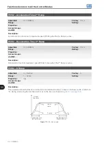
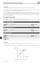
P0106 – Time of the 3
rd
Ramp
Adjustable
Range:
0.1 to 999.0 s
Factory
Setting:
5.0 s
Properties:
Access Groups
via HMI:
Description:
Acceleration time from zero to maximum speed (P0134) or deceleration from maximum speed (P0134) to zero
when the 3
rd
Ramp is active.
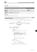
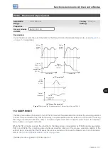
11.2 DC LINK VOLTAGE AND OUTPUT CURRENT LIMITATION
The DC link voltage and output current limitation are protection functions of the inverter which act on the ramp
control according to the P0150 options, aiming at containing the rise of voltage on the DC link and of the output
current. In this way, the following of the reference by the ramp is blocked and the output speed follows the 3
rd
Ramp for P0133 or P0134.
When the DC link voltage is too high, the inverter may freeze (hold) the deceleration ramp or increase the output
speed in order to contain this voltage. On the other hand, when the output current is too high, the inverter may
decelerate or freeze (hold) the acceleration ramp in order to reduce this current. Those actions prevent the
occurrence of faults F0022 and F0070, respectively.
Both protections normally occur at different moments of the inverter operation, but in case of occurrence at the
same time, by definition, the DC link limitation has higher priority than the output current limitation.
There are two modes to limit the DC link voltage during the motor braking: “Ramp Holding” (P0150 = 0 or 2) and
“Accelerate Ramp” (P0150 = 1 or 3). Both actuate limiting the braking torque and power, so as to prevent the
shutting down of the inverter by overvoltage (F0022). This situation often occurs when a load with high moment
of inertia is decelerated or when short deceleration time is programmed.
Содержание CFW500 V1.8X
Страница 2: ......
Страница 4: ......
Страница 8: ...Contents...
Страница 34: ...General Information 2 4 CFW500...
Страница 38: ...About the CFW500 3 4 CFW500 3...
Страница 42: ...HMI and Basic Programming 4 4 CFW500 4...
Страница 52: ...Programming Basic Instructions 5 10 CFW500 5...
Страница 56: ...Identification of the Inverter Model and Accessories 6 4 CFW500 6...
Страница 76: ...Available Motor Control Types 8 4 CFW500 8...
Страница 84: ...V f Scalar Control 9 8 CFW500 9...
Страница 170: ...Communication 17 8 CFW500 17...