


V/f Scalar Control
CFW500 | 9-7
9
9.2 START-UP IN V/f MODE
NOTE!
Read chapter 3 Installation and Connection of the user’s manual before installing, powering up or
operating the inverter.
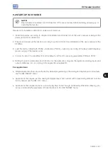
Sequence for installation, verification, power up and start-up.
1. Install the inverter: according to chapter 3 Installation and Connection of the user’s manual, making all the
power and control connections.
2. Prepare and power up the inverter according to section 3.2 Electrical Installation of the user’s manual of the
CFW500.
3. Load the factory default with P0204 = 5 (60 Hz) or P0204 = 6 (50 Hz), according to the input rated frequency
(power supply) of the inverter used.
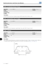
4. In order to set a V/f curve different from the default, set the V/f curve using parameters P0136 to P0147.
5. Setting of specific parameters and functions for the application: program the digital and analog inputs and
outputs, HMI keys, etc., according to the application requirements.
For applications:
Simple applications that can use the factory default programming of the analog and digital inputs and outputs,
use the HMI “BASIC” menu.
Applications that require just the analog and digital inputs and outputs with programming different from the
factory default, use the HMI “I/O” menu.
Applications that require functions such as Flying Start, Ride-Through, DC Braking, Rheostatic Braking, etc.,
access and modify the parameter of those functions in the HMI “PARAM” menu.
Содержание CFW500 V1.8X
Страница 2: ......
Страница 4: ......
Страница 8: ...Contents...
Страница 34: ...General Information 2 4 CFW500...
Страница 38: ...About the CFW500 3 4 CFW500 3...
Страница 42: ...HMI and Basic Programming 4 4 CFW500 4...
Страница 52: ...Programming Basic Instructions 5 10 CFW500 5...
Страница 56: ...Identification of the Inverter Model and Accessories 6 4 CFW500 6...
Страница 76: ...Available Motor Control Types 8 4 CFW500 8...
Страница 84: ...V f Scalar Control 9 8 CFW500 9...
Страница 170: ...Communication 17 8 CFW500 17...