


Fault and Alarms
CFW500 | 15-1
15
15 FAULTS AND ALARMS
The problem detection structure in the inverter is based on the fault and alarm indication.
In case of fault, the locking the IGBTs and motor stop by inertia will occur.
The alarm works as a warning for the user of critical operating conditions and that may cause a fault if the situation
is not corrected.
Refer to chapter 6 Troubleshooting and Maintenance of the CFW500 user’s manual and
REFERENCE OF PARAMETERS, ALARMS AND FAULTS on page 0-1
contained in this manual to obtain more
information regarding the faults and alarms.
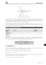
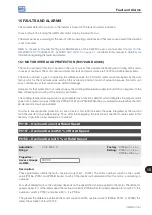
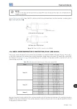
15.1 MOTOR OVERLOAD PROTECTION (F0072 AND A0046)
The motor overload protection is based on the use of curves that simulate the heating and cooling of the motor
in cases of overload. The motor overload protection fault and alarm codes are F0072 and A0046 respectively.
The motor overload is given considering the reference value In x FS (motor rated current multiplied by the duty
factor), which is the maximum value at which the overload protection must not actuate, because the motor can
work continuously at that current value without damages.
However, for that protection to actuate properly, the winding-temperature supervision (which corresponds to the
time of heating and cooling of the motor) is estimated.
This winding-temperature supervision is approximated by a function called Ixt, which integrates the output current
value from a level previously defined by P0156, P0157 and P0158. When the accumulated value reaches the limit,
an alarm and/or fault are indicated.
In order to ensure greater protection in case of restart, this function keeps the value integrated by the function
lxt in the inverter non-volatile memory. Thus, after the energizing, the function will use the Ixt value saved in this
memory to perform a new evaluation of overload.
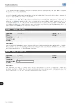
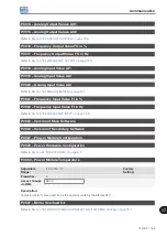
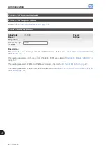
P0156 – Overload Current at Rated Speed
P0157 – Overload Current 50 % of Rated Speed
P0158 – Overload Current 5 % of Rated Speed
Adjustable
Range:
0.0 to 200.0 A
Factory
Setting:
P0156 = 1.1 x I
nom
P0157 = 1.0 x I
nom
P0158 = 0.8 x I
nom
Properties:
Access Groups
via HMI:
MOTOR
Description:
These parameters define the motor overload current (Ixt - F0072). The motor overload current is the current
value (P0156, P0157 and P0158) based on which the inverter will understand that the motor is operating in
overload.
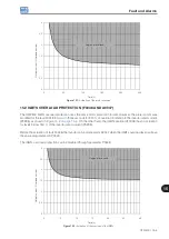
For self-ventilated motors, the overload depends on the speed that is being applied to the motor. Therefore, for
speeds below 5 % of the rated speed the overload current is P0158, while for speeds between 5 % and 50 % the
overload current is P0157, and above 50 %, it is P0156.
The greater the difference between the motor current and the overload current (P0156, P0157 or P0158), the
faster the actuation of fault F0072.
Содержание CFW500 V1.8X
Страница 2: ......
Страница 4: ......
Страница 8: ...Contents...
Страница 34: ...General Information 2 4 CFW500...
Страница 38: ...About the CFW500 3 4 CFW500 3...
Страница 42: ...HMI and Basic Programming 4 4 CFW500 4...
Страница 52: ...Programming Basic Instructions 5 10 CFW500 5...
Страница 56: ...Identification of the Inverter Model and Accessories 6 4 CFW500 6...
Страница 76: ...Available Motor Control Types 8 4 CFW500 8...
Страница 84: ...V f Scalar Control 9 8 CFW500 9...
Страница 170: ...Communication 17 8 CFW500 17...