


7
ASSEMBLY
Note: You may now roll or drive your tractor off the skid.
Follow the ap pro pri ate instruction below to remove the
tractor from the skid
.
TO ROLL TRACTOR OFF SKID (See Op-
er a tion section for location and function of
con trols)
• Press lift lever plunger and raise attachment lift lever
to its highest po si tion.
• Release parking brake by de press ing clutch/brake
ped al.
• Place freewheel control in "trans mis sion dis en gaged
position" (See “TO TRANS
PORT” in the Op
er a tion
section of this manual).
• Roll tractor forward off skid.
• Remove banding holding the defl ector shield up against
tractor.
TO DRIVE TRAC
TOR OFF SKID (See Op-
er a tion section for location and function of
con trols)
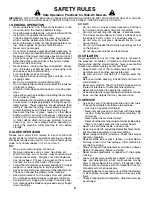
WARNING:
Before start ing, read, un der stand and fol low
all in struc tions in the Op er a tion section of this man u al. Be
sure tractor is in a well-ventilated area. Be sure the area in
front of tractor is clear of other peo ple and objects.
• Be sure all the above assembly steps have been com-
pleted.
• Check engine oil level and fi ll fuel tank with gasoline.
• Place freewheel control in "trans mis sion en
gaged"
po si tion (see "TO TRANSPORT" in Op er a tion section
of this manual).
• Sit on seat in operating position, depress clutch/brake
pedal and set the parking brake.
• Place motion control lever in neutral (N) position.
• Press lift lever plunger and raise attachment lift lever
to its highest position.
• Start the engine. After engine has started, move throttle
control to idle position.
• Release parking brake.
• Slowly move the mo tion control lever for ward and slowly
drive tractor off skid.
• Apply brake to stop trac tor, set park ing brake and place
motion con trol lever in neutral po si tion.
• Turn ignition key to "STOP" position.
Continue with the in struc tions that follow.
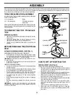
FIG. 2
ADJUSTMENT
BOLT
LOCK WASHER
02466
02465
SEAT PAN
SHOULDER
BOLT
FLAT WASHER
SEAT
FIG. 3
CHECK BATTERY (See Fig. 3)
• Lift seat pan to raised position.
• If this battery is put into service after month and year
indicated on label (label located between terminals)
charge battery for minimum of one hour at 6-10 amps.
(See "BATTERY" in MAINTENANCE section of this
manual for charging instructions).
SEAT PAN
LABEL
• Get off seat without moving its adjusted position.
• Raise seat and tighten adjustment bolt securely.