

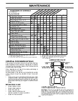


19
SUSPENSION
ARMS
RETAINER SPRINGS
(BOTH SIDES)
RETAINER SPRING
ANTI-SWAY BAR
HOUSING GUIDE
FRONT LINK
COLLAR
ENGINE PULLEY
LARGE RETAINER
SPRING
CLUTCH SPRING
SMALL RETAINER SPRING
BRACKET
SQUARE HOLE
DEFLECTOR SHIELD
SMALL RETAINER SPRING
CLUTCH SPRING
FLAT WASHER
SERVICE AND ADJUSTMENTS
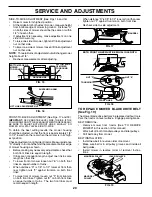
FIG. 14
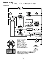
TRACTOR
WARNING: TO AVOID SERIOUS INJURY, BEFORE PERFORMING ANY SER
VICE OR AD
JUST -
MENTS:
•
Depress clutch/brake pedal fully and set parking brake.
•
Place motion control lever in neutral (N) position.
•
Place attachment clutch in “DISENGAGED” position.
•
Turn ignition key to “STOP” and remove key.
•
Make sure the blades and all moving parts have completely stopped.
•
Disconnect spark plug wire from spark plug and place wire where it cannot come in contact
with
plug.
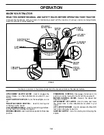
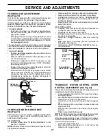
TO REMOVE MOWER (See Fig. 14)
Mower will be easier to remove from the right side of trac-
tor.
• Place attachment clutch in “DIS EN GAGED” position.
• Move attachment lift lever forward to low er mower to
its lowest po si tion.
• Roll belt off engine pulley.
• Remove small retainer spring, and remove clutch spring
off pulley bolt.
• Remove large retainer spring, slide col lar off and push
housing guide out of brack et.
• Disconnect anti-swaybar from chas sis bracket by re-
mov ing re tain er spring.
• Disconnect suspension arms from rear deck brackets
by removing retainer springs.
• Disconnect front links from deck by re mov ing retainer
springs.
• Raise lift lever to raise suspension arms. Slide mower
out from under tractor.
IMPORTANT:
IF AN ATTACHMENT OTHER THAN THE MOWER
DECK IS TO BE MOUNTED ON THE TRAC TOR, REMOVE THE
FRONT LINKS AND HOOK THE CLUTCH SPRING INTO SQUARE
HOLE IN FRAME.
TO INSTALL MOWER (See Fig. 14)
• Raise attachment lift lever to its high est position.
• Slide mower under tractor with defl ector shield to right
side of tractor.
• Lower lift lever to its lowest po si tion.
• Connect front links to mower deck and secure with
retainer springs..
• Connect suspension arms to rear deck brackets and
secure with retainer springs.
• Connect anti-swaybar to chassis bracket and secure
with retainer spring.
• Push clutch cable housing guide into bracket, slide col-
lar onto guide and secure with large retainer spring.
• Place fl at washer and clutch spring on idler pulley bolt
and secure with small retainer spring.
• Install belt onto engine pulley.
TO LEVEL MOWER HOUSING
Adjust the mower while tractor is parked on level ground
or driveway. Make sure tires are properly infl ated (See
“PROD UCT SPECIFICATIONS” section of this manual). If
tires are over or underinfl ated, you will not properly adjust
your mower.