background image

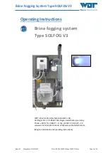
Brine Fogging System Type SOLFOG V3 

Index: 02 

Change date: 19/09/2023 

OI No.: BA DW 042-02 Solfog V3 CB36 EN.docx 

Page 5 of 65 

1


About these instructions / general 

1.1


Scope of applicability 

These Operating and Installation Instructions describe the function, installation, commissioning 
and operation of the foam brine fogging system type SOLFOG V3. They must be read carefully 
before use and kept on the device for direct use, so that they are available at any time! 

These Operating and Installation Instructions are an integral part of the device. If the product is 
resold, the Operating Instructions must be handed over to the new operator. 

If  you  lose  the  documentation,  you  can  download  it  from  our  website  at:  

www.werner-dosiertechnik.de/Produkte/Wellness/Vernebelung-von-Soleloesung


1.2


Target group 

Only our  authorised  partners  and  people  who  have been  trained  in  the  device  functions  are 
permitted to work on the system. 

WARNING! 

Danger of electric shock! 

The system is under life-threatening voltage even during downtime! 


Electrical connection work may only be carried out by appropriately trained 
specialists! 

1.3


Symbols used 

This document uses the following types of safety notices as well as general notices: 

DANGER! 

“DANGER” denotes a safety notice which, if disregarded, will lead to serious or life-
threatening injuries or death! 

WARNING! 

“WARNING” denotes a safety notice which, if disregarded, may lead to serious or 
life-threatening injuries or death! 

WARNING! 

Danger of electric shock! 

This safety notice denotes danger due to electric shock, which, if disregarded, may 
lead to serious or life-threatening injuries or death! 


Содержание SOLFOG V3

Страница 1: ...1 of 65 Operating Instructions Brine fogging system Type SOLFOG V3 WDT Werner Dosiertechnik GmbH Co KG Hettlinger Str 17 D 86637 Wertingen Geratshofen Germany Phone 49 82 72 9 86 97 0 Fax 49 82 72 9...

Страница 2: ...entification plate on the device at hand Reproduction of any kind and translation into other languages even in excerpts is only permit ted with the express authorisation of the company WDT Werner Dosi...

Страница 3: ...3 4 5 Button plate option 14 3 4 6 Lighting system for fog outlet option 15 3 5 Technical data 15 4 Transport and storage 16 4 1 General safety notices 16 4 2 Packaging 16 4 3 Temporary storage of the...

Страница 4: ...ice information 45 8 7 15 Display data log 45 8 7 16 Conduct a reset 46 8 7 17 Config set password protection 46 8 7 18 Set Config Push button illumination 47 8 8 Change the brine solution 48 8 9 Repl...

Страница 5: ...w werner dosiertechnik de Produkte Wellness Vernebelung von Soleloesung 1 2 Target group Only our authorised partners and people who have been trained in the device functions are permitted to work on...

Страница 6: ...cautions for ESD sensitive devices must be ob served when handling the devices NOTICE A Notice denotes information that is of particular importance for the smooth running of op erations and that can d...

Страница 7: ...livery subject to correct installation and commissioning with a completed and signed commissioning protocol Exempt from this are wear parts such as seals hoses diaphragms dosing screws electrodes roll...

Страница 8: ...formation regarding support queries identification plate The control unit of the brine fog maker type SOLFOG V3 is subject to continued further devel opment of both its firmware and hardware We always...

Страница 9: ...ation after decommissioning Commissioning Operation Maintenance servicing Disposal The attachment or installation of additional equipment is only permitted with the manufac turer s written approval Pa...

Страница 10: ...power supply and se cure them against being reactivated Pay attention to the warning notices on the device After corresponding electrical installation or repair test all protective measures used e g e...

Страница 11: ...ignition sources e g hot surfaces sparking open fire or cigarettes Carefully read and pay attention to the operating instructions prior to installation and use of the device In the event of malfunctio...

Страница 12: ...number on the identification plate correspond to the details in the order ing and delivery documents and the equipment is complete and all parts are in perfect condition In the event of any transport...

Страница 13: ...onnected cabin By default the device is started with the main switch Optionally the device can be controlled via a push button from the cabin or via an external signal Operation without brine If the S...

Страница 14: ...ose the fragrance container Fig 1 No 15 must be filled up to the mark max 50 ml with a fragrance oil concentrate for room scenting and a filter star must be inserted The fan Fig 1 No 13 blows the evap...

Страница 15: ...ed washer at the fog outlet into the cabin SOLFOG V3 Dimensions and weights External dimensions WxHxD 0 40 x 0 71 x 0 25 m Space requirement WxHxD 0 50 x 0 90 x 0 30 m Space requirement including op e...

Страница 16: ...particular plastic bags out of reach of children NOTICE Please pay attention to the notices and pictograms attached to the carton 4 3 Temporary storage of the device ATTENTION Damage to the device due...

Страница 17: ...ion site Installation is only permitted in the technical room Pay attention to the information regarding the installation site and the tech nical room in the technical data on page 14 The installation...

Страница 18: ...At unsuitable walls e g porous or unstable or with inadequately dimensioned fas tening material e g screws that are too short or unsuitable dowels the device may detach from the wall Pay attention to...

Страница 19: ...ystem Fig 8 Installation plan SOLFOG V3 without lighting system Installation with lighting system Fig 9 Installation plan SOLFOG V3 with lighting system Cabin wall Cabin Technical room Minimum gradien...

Страница 20: ...n of larger germ concentrations Piping without fog lighting system To install the piping proceed as follows 1 Find a suitable location for the fog inlet into the cabin 2 Drill a 40 mm hole in the cabi...

Страница 21: ...ter Maximum line length 4 m Connect the special bend with the vertical fog maker pipe and connect it to the SOLFOG s outlet pipe Pay attention to the gradient in the line 4 Push the lighting rod into...

Страница 22: ...os 11 is provided on the mounting plate 2 Connect the SOLFOG to the power supply 110 230 V AC 50 60 Hz with the power plug 6 3 Additional connection options The following additional connection options...

Страница 23: ...il concentrates only for room scenting with the SOLFOG Keep out of the reach of children Do not allow to come into contact with skin or eyes Wear chemical resistant protective gloves and goggles ATTEN...

Страница 24: ...ey only reactivates the backlighting 7 5 Insert the roller carrier at the fragrance pump WARNING Risk of crushing Injury to fingers crushing possible Only conduct the work when the device has been swi...

Страница 25: ...ulty operation Fig 13 Peristaltic pump 31 Transparent pump cover not shown 32 Safety disc 33 Hose bracket with dosing hose hose bracket kit 34 Roller carrier covered 35 Pump casing 41 Suction connecti...

Страница 26: ...to the factory settings the language and the parameters for pause time fogging time and operation mode must first be entered The corresponding displays are shown in sequence After successful entry th...

Страница 27: ...be documented in the disinfection protocol and a disinfection must be carried out at start of operation 28 days operation CAUTION Health hazard due to limited shelf life of the brine After opening the...

Страница 28: ...een started can only be cancelled by switching it off at the main switch After that the message Disinfection necessary is displayed every time the device is switched on The display Disinfection necess...

Страница 29: ...it directly into the drain Pay attention to the nationally applicable regulations for environmental and drinking water protection Fig 21 Menu Rinse fog maker container 3 Loosen the two cable couplings...

Страница 30: ...ting plug in the politainer connection Fig 26 Push the politainer into the console 12 Turn the connected politainer upside down and push it into the console Ensure that the yellow flange ring rests in...

Страница 31: ...c pump delivers the disinfection solution into the fog maker container until the required fill level is reached The disinfection solution is vaporised by the ultrasonic fog maker and blown through the...

Страница 32: ...ntainer 19 Pull the Fog maker container Fig 13 No 19 forwards out of the bracket and remove it downwards 20 Empty the fog maker container rinse it with drinking water and then replace the empty fog ma...

Страница 33: ...ld the empty brine politainer in your hand with the lid pointing upwards 3 Unscrew the politainer connection from the empty politainer 4 Take a new brine politainer 1 kg or 5 kg hold it with the lid p...

Страница 34: ...r and allergic reactions Undiluted fragrance oil concentrates may cause irritation and allergic reactions Do not drink smoke or rub in Use fragrance oil concentrates only for room scenting with the SO...

Страница 35: ...display 8 4 Switching on off NOTICE When the device is switched on for the first time after commissioning or after a reset it starts automatically with the start query see Chapter 7 7 1 on page 26 Th...

Страница 36: ...rt the commissioning with a disinfection 8 5 Button plate function 8 6 Fog lighting function Fig 39 Button plate sample illustration Start the programme Fog generation After pressing the button the SO...

Страница 37: ...y to the test menus output test input test These must be actively exited A start button option can be plugged into a socket on the control housing as desired Fig 41 Menu sequence Pressing any Key Fig...

Страница 38: ...e display shows the opera tion display Depending on the operation mode the operation display shows the corresponding information In Figure 43 top Push button operation mode In Figure 43 bottom Exter n...

Страница 39: ...an only be cancelled by switching off at the main switch Notice If the Disinfection menu is exited with Esc the display returns to the main menu Fig 45 Menu Pause time The pause time denotes the time...

Страница 40: ...via the push button option in the cabin and operated for the set push button cycle time with the settings of the pause and fogging time 8 7 6 Set push button cycle Fig 49 Illustration push button cyc...

Страница 41: ...h the Enter key 2 Use the arrow keys to select the speed in percent and save with the Enter key The display returns to the main menu Fig 51 Menu Test outputs You can test the different electrical outp...

Страница 42: ...inputs entry in the main menu and confirm with the Enter key The inputs are marked with a red circle on the right side Filled circle Input active Empty circle Input inactive Depending on the connectio...

Страница 43: ...y switches back to the selection of Time or Date 5 In the overview select the Esc entry to navigate to the main menu Fig 55 Menu Timer weekly overview The timer function can be switched on and off wit...

Страница 44: ...ue 4 Once the last possible entry has been confirmed the display switches back to the selection of the week day Use Esc to navigate to the higher level Timer menu 5 Select the Timer entry menu and con...

Страница 45: ...r key The display returns to the main menu Fig 59 Menu Info You can display the device information in this submenu 1 Select the Info entry in the main menu and confirm with the Enter key The display s...

Страница 46: ...e Enter key 3 Select the Yes entry using the arrow keys and confirm the entry with the Enter key Fig 62 Menu Config Password The Config menu can be found at the very bottom of the main menu In the Con...

Страница 47: ...the push button Ex works setting is button with the button setting the button illumination and the fog lighting are inverted see wiring diagram Dimming of the fog lighting is not provided Settings exa...

Страница 48: ...anging the brine politainer please pay attention to Chapter 0 on page 33 8 9 Replenish fragrance oil concentrate WARNING Danger of irritation or and allergic reactions Undiluted fragrance oil concentr...

Страница 49: ...f necessary or use a new fragrance container 3 Insert a clean filter star Fig 64 No 81 in the fragrance container Fill the desired fragrance concentrate into the fragrance container up to the fill lev...

Страница 50: ...d e g earthing resistance ATTENTION Danger due to static charge This safety notice denotes electronic components that may be damaged by electro static discharges The generally accepted safety precauti...

Страница 51: ...fe and storage time WARNING Health hazard due to germ contamination Over aged brine solution can lead to the formation of germs which can enter the ap plication room via the fogging and be inhaled the...

Страница 52: ...amage e g cracks discolouration in due time and to replace the dosing hose The dosing hose must be replaced at least every 6 months Fig 66 Individual components of the peristaltic pump 9 3 1 Replace h...

Страница 53: ...e visible in the front and centre see Fig 67 Fig 67 Hose bracket kit marking 1 Disassemble hose bracket kit see Chapter 7 5 on page 24 2 To replace the dosing hose Fig 67 No 43 at the hose bracket Fig...

Страница 54: ...he device must be carried out by specialist personnel only All electrical installations and any work on the device s electrical components must be carried out by authorised electricians only Prior to...

Страница 55: ...w politainer Check peristaltic pump Check level control plug Filling time has expired Brine politainer empty Peristaltic pump does not work Level control plug un plugged defective Renew politainer Che...

Страница 56: ...ct setting on the push button illumination Renew fuse Check electrical connection Correct settings in the Config menu No discernible scent Fragrance container empty dried up Fuse defective Fan defecti...

Страница 57: ...head with a soft cloth microfibre cloth Remove and dispose of the brine politainer Remove the brine pump s roller carriers to avoid any damage to the dosing hose see Chapter 7 5 on page 24 Prior to an...

Страница 58: ...o the national and local laws ordinances and regulations re garding the disposal of mechanical and electronic components Pay attention to the following notices when disposing of the device Thoroughly...

Страница 59: ...Brine Fogging System Type SOLFOG V3 Index 02 Change date 19 09 2023 OI No BA DW 042 02 Solfog V3 CB36 EN docx Page 59 of 65 11 Documents 11 1 Declaration of conformity...

Страница 60: ...Brine Fogging System Type SOLFOG V3 Index 02 Change date 19 09 2023 OI No BA DW 042 02 Solfog V3 CB36 EN docx Page 60 of 65 11 2 Wiring diagrams...

Страница 61: ...Brine Fogging System Type SOLFOG V3 Index 02 Change date 19 09 2023 OI No BA DW 042 02 Solfog V3 CB36 EN docx Page 61 of 65...

Страница 62: ...64 11 4 Operation data sheet NOTICE During commissioning enter the operating parameters in the operation data sheet Menu Factory setting Setting range Step During commissioning Date Optimised during o...

Страница 63: ...hazard due to germ contamination Over aged brine solution can lead to the formation of germs which can enter the ap plication room via the fogging and be inhaled there Carry out a disinfection every...

Страница 64: ...Item Designation Code no WDT Peristaltic pump Cover for pump casing Sa transparent 14259 Safety disc for roller carrier Sa grey 13633 Hose bracket with hose SA 3 2x1 6 Ph 13260 Gear motor to peristal...

Страница 65: ..._____________________________________________________ ____________________________________________________________________________ _____________________________________________________________________...

Страница 66: ......

Страница 67: ...2 Device and lines checked for leaks 1 3 Fog line with a maximum length of 4 m with gradient toward the brine fog maker 1 4 Roller carrier inserted according to OI Chapter 7 5 1 5 Disinfection carried...

Страница 68: ......

Страница 69: ...1 2 Clean fog maker diaphragm with a soft cloth 1 1 3 Grease O ring on top of the fog maker container 1 1 4 Check peristaltic pump for function and leaks 1 1 5 Check device for leaks and conduct a vis...

Страница 70: ......

Страница 71: ...recess to sink the sealing flange with a depth of 3mm Dimensions 1 fold HxW min 130x97mm 2 fold HxW min 163x97mm 3 fold HxW min 196x97mm 4 fold HxW min 229x97mm d Break out an orifice for the empty co...

Страница 72: ...uilding foam in the wall approximately 20 mm protruding due to flush system Insert cable d Install the supplied construction protection cap in the flush mounted box e Plaster the brickwork so that the...

Отзывы: