Waygate Technologies Krautkramer USM 10 Скачать руководство пользователя страница 82

82

Rev. - (09/2021)

Krautkrämer USM 100

Settings

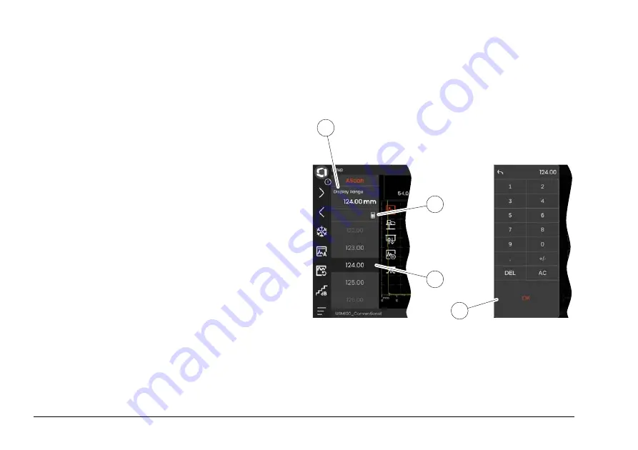
Many functions are parameters for which you can set a 
value, for example the 

Display Range

.

– Select the panel 

Setup

 and display the function 

group 

A-scan

 (see page 79). The functions and their 

current settings are displayed.

– Tap on the function 

Display Range

 (1). The value se-

lector is displayed.

– Swipe the selector up or down to show the possible 

values. The highlighted value in the center (3) is ap-
plied immediately without further saving. Depending 
on the parameter, the effect is immediately visible in 
the A-scan.

– Tap the calculator icon (2). A numeric keypad is dis-

played.

– Tap the digits to enter the required value. 

– Tap 

OK

 (4) to complete the entry. The numeric key-

pad is hidden and the value is applied.

– Tap the function name (1) to close the value selector. 

1

4

3

2

Содержание Krautkramer USM 10

Страница 1: ...Krautkr mer USM 100 Operating Manual Id No 160M4395 Rev 09 2021...

Страница 2: ...ptember 2021 You will find the software version and the serial number of your instrument in the About section see page 104 in the General Settings menu see page 99 Baker Hughes Digital Solutions GmbH...

Страница 3: ...t panel Select the Gain Step see page Switch to the previous panel Magnify Gate see page A scan freeze Freeze see page 66 Pause data recording Set the echo to defined screen height AutoXX see page 66...

Страница 4: ...021 Krautkr mer USM 100 Command bar continued Quick save Export CSV file Load settings Save screen capture Save settings Save report Load data Save multiple page report Save data Lock the touchscreen...

Страница 5: ...s An alphabetical list of all functions in the function groups can be found in the UT Function directory see page 206 A Scan Auto Calibration Material Probe Probe Angle Pulser Receiver Evaluation UT S...

Страница 6: ...at surface reflection from the backwall DGS reference echo has been recorded transfer loss 0 Pulser receiver separation is turned off Angle probe 30 curved surface reflection from the inner surface dB...

Страница 7: ...al Second Battery is charged remaining operating time in hours approx value Battery charge level remaining operating time in hours approx value Warning Low battery charge Battery is empty Power adapte...

Страница 8: ...e down on a menu or list increment a numeric parameter 4 Navigate between major areas of the screen to select items for action 5 On the back Increase gain or move right 6 On the back Decrease gain or...

Страница 9: ...measurement 26 Effect of the test object material 26 Effect of temperature variations 27 Measurement of remaining wall thickness 27 Ultrasonic evaluation of flaws 27 Flaw boundary method 27 Echo displ...

Страница 10: ...ation 70 Function groups and functions 73 Main functions sidebar 74 Status indicators 75 Measurement line 76 Information line 77 4 4 Operation with touchscreen 78 Executing or selecting a function 78...

Страница 11: ...ine Gain 108 5 8 A Scan 109 Display Range 109 Display Delay 110 Probe Delay 110 Velocity 110 Freeze Mode 111 Envelope 112 Envelope Color 112 Grid 112 Amplitude Ruler 112 Range Ruler 113 A Scan Color 1...

Страница 12: ...5 11 UT Setup 123 Gain 123 AGC Mode 123 AGC Max Amp AGC Min Amp 124 AGC Noise 124 Alarm Output 124 LED Alarm 124 Averaging 124 Magnify gate 125 Analog Output 125 5 12 Gates 126 Tasks of the gates 126...

Страница 13: ...al Type 135 2 Point Cal Source 135 S Ref 1 S Ref 2 135 5 14 Probe Angle 136 Block 136 Angle Cal Source 137 SDH Diameter 137 SDH Depth 137 Gate A Start 137 Gate A Threshold 137 5 15 Evaluation 138 Eval...

Страница 14: ...Line 144 5 16 Calibration 145 Calibrating the probe delay and velocity 145 Choice of the measuring point 145 Calibration with Multi BW 146 Calibration with Multi Step 147 Calibration using dual elemen...

Страница 15: ...1 1 AWS D1 5 171 5 22 JISDAC 174 5 23 CNDAC 175 Evaluations according to CNDAC 175 Standards and reference blocks 176 6 Documentation 6 1 Test reports 178 Saving test reports 178 Printing test reports...

Страница 16: ...tes 196 Installing an update 196 Update in case of malfunction 197 7 5 License upgrade 198 8 Interfaces and Peripherals 8 1 Interfaces 200 Overview 200 USB A interface 201 USB C interface 201 WLAN 202...

Страница 17: ...Contents Krautkr mer USM 100 Rev 09 2021 17 10 Specifications General features 220 Environmental 221 Display 221 Interfaces 222 Transmitter 222 Receiver 223 Data acquisition 224 Gates 224 11 Index...

Страница 18: ...18 Rev 09 2021 Krautkr mer USM 100...

Страница 19: ...Krautkr mer USM 100 Rev 09 2021 19 Introduction 1...

Страница 20: ...P67 per IEC 60529 1 It can be operated ei ther with the corresponding lithium ion batteries or with the power adapter The power adapter meets the re quirements of electrical safety class II ATTENTION...

Страница 21: ...ot swappable lithium ion battery either within the instrument itself or in an external char ger If the lithium ion battery is inserted charging starts automatically as soon as you connect the power ad...

Страница 22: ...te Tech nologies representative Defects errors and exceptional stresses If you have reason to believe that a safe operation of your USM 100 is no longer possible you have to discon nect the instrument...

Страница 23: ...h the limits for a Class A digital device pursuant to Part 15 of the FCC Rules These limits are designed to provide reasonable protection against harmful interfer ence when the equipment is operated i...

Страница 24: ...ee most important pre requisites for a safe and reliable ultrasonic inspection are Operator training Technical test requirements and limits Choice of appropriate test equipment Operator training The o...

Страница 25: ...erstood by the inspector Waygate Technologies regularly holds specialized train ing courses in the field of ultrasonic testing The sched uled dates for these courses will be given to you on re quest L...

Страница 26: ...e g nonferrous metals or plastics the sound velocity variations may be even larger and thus affect the measuring accuracy Effect of the test object material If the material of the test object is not h...

Страница 27: ...ndling the probe The inspectors should always be informed about the corresponding nominal wall thicknesses and the likely amount of wall thickness losses Ultrasonic evaluation of flaws In present day...

Страница 28: ...large components Pay close at tention to choosing artificial comparison flaws which are as far as possible governed by the same distance laws as the natural flaws to be evaluated The ultrasonic wave i...

Страница 29: ...luding aerospace power generation automotive as well as oil and gas General features Truly ambidextrous flip function 7 inch color LCD display 1 024 x 600 pixels Operation with touchscreen and keypad...

Страница 30: ...ometric calculations with curvature correction for weld inspection Color coded data logger 10 000 points including A scan Evaluation modes Dynamic DAC TCG AWS D1 1 D1 5 dB Ref DGS JISDAC CNDAC 200 amp...

Страница 31: ...aluation modes Dynamic DAC TCG AWS D1 1 D1 5 dB Ref DGS JISDAC CNDAC 400 amplitude range for gate measurement Configurable sidebar for placement of critical parameters Alphanumeric on screen keyboard...

Страница 32: ...400 amplitude range for gate measurement Configurable sidebar for placement of critical parameters Alphanumeric on screen keyboard for file naming Support for unlimited on device apps at a time 3rd g...

Страница 33: ...all keys and displays and explain the operating principle In doing this you will avoid any errors or failures of the instrument and be able to use the full range of instru ment functions To find infor...

Страница 34: ...1 Introduction How to use this manual 34 Rev 09 2021 Krautkr mer USM 100...

Страница 35: ...Krautkr mer USM 100 Rev 09 2021 35 Standard package and accessories 2...

Страница 36: ...nstrument Package 150M5734C USM 100 Standard Instrument with CERT Same as 150M5734 with ISO Certificate 150M5735 USM 100 Pro Instrument USM 100 Pro Instrument Package 150M5735C USM 100 Pro Instrument...

Страница 37: ...strap USB C dock Quick Start Guide Operating Manual on USB flash drive Certificate Of Conformity DOES NOT INCLUDE power cord Power cord needs to be ordered separately USM 100 Pro accessories AC adapte...

Страница 38: ...DOES NOT INCLUDE power cord Power cord needs to be ordered separately 148M5839 USM 100 SW OPT Pro Upgrade USM 100 Standard to USM 100 Pro 148M5840 USM 100 SW OPT Digital USM 100 InspectionWorks subscr...

Страница 39: ...ini quadrature encoder MUT ODI SINGLEPROB Mentor UT Scanner in Confined Spaces Mini quadrature encoder 0029017 Couplant Couplant 159M0219 I O open end cable I O cable 14 pin Lemo to open end 148M5830...

Страница 40: ...or USM 100 022 505 604 PTPA CBL MD 00LEMO RA 6 Right angle Lemo 00 to Microdot cable 022 509 819 CABLE LEMO 00 RT ANG LEMO 00 Right angle Lemo 00 to Lemo 00 cable 022 509 820 CABLE LEMO 00 RT ANG LEMO...

Страница 41: ...0 90 TR plug 0112730 CABLE Probe cable 2 Lemo 00 90 Subvis twin 0112745 CABLE LEMO 00 R SINGLE 0540339 Probe cable Lemo 00 90 Subvis 0058160 CTPA CL331 Probe cable Lemo 00 Microdot 0058791 PROBE CABLE...

Страница 42: ...ltrasonic Testing Level II 021 999 196 UT Levels I II Practical Training E UT Levels I II Practical Training a supplement to eLearning 021 999 245 Ultrasonic Testing Level I Ultrasonic Testing Level I...

Страница 43: ...Krautkr mer USM 100 Rev 09 2021 43 Initial start up 3...

Страница 44: ...ly The USM 100 can be operated either with the external power adapter or with one internal or two internal and second lithium ion batteries You can also connect the USM 100 to the mains power supply i...

Страница 45: ...n the Lemo plug of the power adapter with the socket 1 Push the plug into the socket until it locks into place with a clearly audible click When removing the Lemo plug pull the metal sleeve on the plu...

Страница 46: ...TENTION Only lithium ion batteries recommended and supplied by Waygate Technologies may be used for instrument operation Changing the battery The battery compartment is located on the bottom of the in...

Страница 47: ...battery compartment as described above and carefully pull the battery out by the tab 3 Checking the charge level of the lithium ion battery The lithium ion battery is provided with a battery charge l...

Страница 48: ...ft battery symbol 1 represents the internal bat tery the right symbol 2 the hot swappable second bat tery The USM 100 is automatically powered off if the opera tion is no longer ensured ATTENTION If t...

Страница 49: ...nternal Second Battery is charged remaining operating time in hours approx value Battery charge level remaining operating time in hours approx value Warning Low battery charge Battery is empty Power a...

Страница 50: ...ains power supply You can carry out ultrasonic tests and charge the batteries at the same time The charging time is approx ten hours with simultane ous ultrasonic testing If the instrument is not used...

Страница 51: ...n sequence would be a mismatching which may lead to considerable power losses or even to echo waveform distortions The probe is connected to the sockets on the right side of the instrument Connect a s...

Страница 52: ...100 3 4 Inserting a USB stick You can use any USB stick for data transfer to and from the USM 100 Slide the lid 1 on the top of the instrument to the right side until it swings open upwards Insert th...

Страница 53: ...b to connect the USM 100 to the LAN network and connect other periph erals monitor mouse keyboard to the instrument For more information on interfaces see from page 200 Slide the lid 1 on the top of t...

Страница 54: ...setting after switching on the instrument and system boot up you will see the Application desk top see page 61 with all applications stored in the in strument and available for selection Depending on...

Страница 55: ...ries are completely discharged the operation does not end cor rectly The settings of all function values and the default set tings language and units are retained after powering off Select the Main Me...

Страница 56: ...VNC client USB C hub with RJ45 connector Network cable VNC Client To view and control the instrument s screen remotely you must have a VNC client installed on your computer As VNC is a standard protoc...

Страница 57: ...e computer with installed VNC client must be con nected to the same network Settings in the USM 100 An overview of the remote connection settings can be found from page 104 Tap the Main Menu icon see...

Страница 58: ...he USM 100 see page 57 Launch the VNC client for example the RealVNC viewer Enter the IP address of the USM 100 in the address field and press the Enter key The connection is established and after a s...

Страница 59: ...Krautkr mer USM 100 Rev 09 2021 59 Principles of operation 4...

Страница 60: ...he basic settings and functions for working with the USM 100 1 Return to the A scan view 2 Application desktop see page 61 3 File management see page 187 4 Mentor server connection only visible if no...

Страница 61: ...or more panels In the factory setting after switching on the instrument and system boot up you will see the Application desk top with all applications stored in the instrument and available for selec...

Страница 62: ...current view in relation to all available pages If necessary swipe the screen to view more applica tions Tap on the icon in the upper right corner of an appli cation box to display a short descriptio...

Страница 63: ...k with one or more application files into the socket on the top of the instrument see page 52 Tap on the Plus icon in the upper left corner of the Application desktop A dialog window opens Tap in the...

Страница 64: ...Before deleting you can back up the applica tions to a USB stick see page 188 The de letion can not be undone Tap on the icon in the upper right corner of an appli cation box to display a short descr...

Страница 65: ...bar see page 66 3 Switching Command bar icons see page 78 4 Panel selector see page 72 5 Function groups and functions see page 73 6 UT function groups icons see page 106 7 Status indicators see page...

Страница 66: ...g When the A scan is frozen the icon is colored and a cor responding status indicator is displayed above the A scan see page 6 at the beginning of the operating man ual You can define the Freeze Mode...

Страница 67: ...ain adjustment using the keys on the back of the instrument The first steps are fixed the last step can be set individually with the function Custom Gain Step see page 108 Magnify Gate This function c...

Страница 68: ...le in the device memory or on an inserted USB stick see page 97 Load data You can load UT settings and data together The A scan will be redrawn on the screen Save data You can save UT settings and dat...

Страница 69: ...ory Save multiple page report You can save a multiple page test report Multiple page test reports are saved in the default directory Lock You can lock the touchscreen to prevent unintended op eration...

Страница 70: ...n can be displayed in normal mode or in zoom mode In the zoom mode the measurement line is not visible The gain can then only be adjusted with the keys on the back of the instrument not with the funct...

Страница 71: ...e displayed as colored areas in the A scan With the function Magnify gate see page 67 in the Command bar you can span a selected gate over the entire displayed range You can select the gate for this f...

Страница 72: ...able by the user and to within what range of values a particular parameter can be set The function groups with their individual functions 3 are divided into different application specific panels for a...

Страница 73: ...you briefly tap in the A scan After a short time the icons are automatically hid den again The functions 1 of a function group are displayed when you tap the corresponding icon The icon of the curren...

Страница 74: ...100 Main functions sidebar Independent of individual function groups you can quickly access the main functions 2 of a specific panel 1 by sliding the sidebar from the left edge of the A scan into the...

Страница 75: ...he top left corner above the A scan You can change the step size for quick gain adjustment with the function Gain step 1 in the Command bar see page 67 Status indicators Above the A scan is the area f...

Страница 76: ...measuring point peak or flank is displayed with a symbol in sound path measurements measuring point Peak measuring point Flank or first flank crossing the gate Examples SA sound path in gate A measur...

Страница 77: ...ne The information line at the bottom of the screen shows various information notes instructions and warnings depending on the situation You can tap on an instruction or warning to hide it Example Inf...

Страница 78: ...to frequently used functions regardless of the specific type of task see page 66 Tap on an icon 1 of the Command bar to execute the corresponding function Swipe the Command bar up or down to display t...

Страница 79: ...display the available function group icons 3 Tap on a function group icon to display the function group 2 with the associated functions Tap on a function name 1 to set a parameter see page 82 or exec...

Страница 80: ...nctions The function group Gain for setting the gain and the related functions is always accessible regardless of the selected panel Above the A scan tap the box 3 that displays the gain The function...

Страница 81: ...1 Functions in the measurement line The measurement line on top of the A scan may also show one or two specific functions 1 You can set these functions directly without having to go via the function g...

Страница 82: ...The value se lector is displayed Swipe the selector up or down to show the possible values The highlighted value in the center 3 is ap plied immediately without further saving Depending on the parame...

Страница 83: ...group Material probe see page 79 The functions and their current settings are displayed Tap on the function Probe Name 1 The list of probe names is displayed Swipe the list up or down to see all list...

Страница 84: ...ghted by a red back ground This incompatibility can occur for instance between the gate start and gate width or if the PRF is too high and the gate is too far out in time If functions in different fun...

Страница 85: ...the lock symbol near the function name Reasons for locked functions can be The application s architect intended the value to be observed but not altered The display is frozen manually see page 66 or...

Страница 86: ...e the entire gate touch the center of the gate The gate border is highlighted Slide the gate to the desired position To change the start or end position or the threshold touch the respective edge of t...

Страница 87: ...est way to set the gain is with the keys on the back 1 Move up on a menu or list decrement a numeric parameter 2 Select an item from a menu or list 3 Move down on a menu or list increment a numeric pa...

Страница 88: ...g you can mark the respective areas on the screen with the keys and then execute the corresponding ac tions with the keys as well Selecting a screen area You can select the various screen areas consec...

Страница 89: ...nction in the next step If the selected area contains several functions you must first select the desired function and can then execute or set the func tion Press the red key repeatedly to mark the Ga...

Страница 90: ...rate the Command bar with the keys as well Press the red key repeatedly to mark the Waygate icon 5 Press the black center key 3 to access the Com mand bar Press the upper 4 or the lower 2 black key to...

Страница 91: ...selected panel see page 72 Press the red key repeatedly to mark the whole A scan area 5 Press the black center key 2 to display the function group icons The first icon is selected 4 Press the upper 3...

Страница 92: ...ct the function Display Range from the function group A scan see page 91 The value selector is displayed Press the upper 3 or the lower 1 black to highlight the required value 4 Press the black center...

Страница 93: ...to the screen gives you var ious information about the device status and special events With the instrument switched off With the instrument switched on Blue The batteries are charged Off Power adapte...

Страница 94: ...4 Principles of operation Multi color LED 94 Rev 09 2021 Krautkr mer USM 100...

Страница 95: ...Krautkr mer USM 100 Rev 09 2021 95 Operation 5...

Страница 96: ...ee page 99 System settings see page 100 Date and Time settings see page 102 Regional settings see page 103 From the function group A Scan see page 109 A Scan Color selection see page 113 Grid Color se...

Страница 97: ...ot contain any of the fol lowing characters From the Command bar tap the Save settings icon see page 68 A dialog box opens Tap in the field Name A keyboard is displayed Enter the name for the file Tap...

Страница 98: ...Note The settings must match the currently loaded application Otherwise an error message is displayed From the Command bar tap the Load settings icon see page 68 A dialog box opens Tap in the field L...

Страница 99: ...autkr mer USM 100 Rev 09 2021 99 5 4 General settings You find all general instrument settings in the General settings menu Tap the Main Menu icon see page 65 to display the Main Menu see page 60 Tap...

Страница 100: ...immediately You can set the color of the A scan separately see page 113 as well as the grid color see page 113 Screen Brightness You can adjust the screen brightness to your working environment with t...

Страница 101: ...st select an application after each start of the instrument see page 61 Autostart to PCLive When connected via LAN network the dedicated soft ware USM 100 PC can be used besides other things to contro...

Страница 102: ...e is set automatically after connecting the instru ment to the Internetvia LAN see page 201 or WLAN see page 202 You cannot change the displayed time Time Zone You must select the appropriate time zon...

Страница 103: ...ance Units You can switch the distance units between METRIC and INCHES any time All values are adjusted accordingly Decimal You can choose the decimal separator mark All data are displayed and saved u...

Страница 104: ...nfigure the instrument for remote control via a network For the complete remote connection setup procedure see page 56 Allow Remote Access You can allow the remote access via the network either for vi...

Страница 105: ...of the measurement line You can make the selection separately for each box Tap on a box 1 in the measurement line A dialog box opens In the left column select a category for example DAC TCG In the mid...

Страница 106: ...nction group you operate these functions The available function groups and functions depend on the panels see page 72 set up in the loaded applica tion see page 61 Note A quick way to find information...

Страница 107: ...e sensitivity necessary for making echoes from reflectors to be detected visible on the display screen at the required height Press the keys on the back of the instrument to in crease or decrease the...

Страница 108: ...ect s surfaces on the height of the echo into account You can determine the value for the transfer correction by experiment For more details on this please read the corresponding technical literature...

Страница 109: ...probe delay must likewise be set Display Range The display range must be adjusted to the sound veloc ity used function Velocity and to the connected probe function Probe Delay The adjustment range for...

Страница 110: ...elay Probe Delay Every probe is equipped with a delay line between the transducer and the coupling face The sound pulse must first pass through this delay line before it can enter the test object You...

Страница 111: ...n dif ficult coupling conditions or for spot weld testing B Freeze The A scan is frozen automatically when the signal touches the gate B This setting is suitable e g for mea surements on hot test obje...

Страница 112: ...can is updated every time the maximum ampli tudes are exceeded A scan with envelope curve Envelope Color You can choose the color of the envelope curve inde pendent of the selected Color Scheme see pa...

Страница 113: ...the TOF values in s Material Depth When using angle probes the material depth is different from the sound path This ruler shows the material depth values A Scan Color You can choose the color of the A...

Страница 114: ...e 100 Ref Envelope Color You can choose the color of the reference envelope curve independent of the selected Color Scheme see page 100 Color Leg For better orientation the instrument can mark the leg...

Страница 115: ...ile name before the au tomatically generated data year month day time With the prefix USM_ for example a file name will then be USM_2021 03 02_16 09 49 Tap on the function name A keyboard is displayed...

Страница 116: ...lar curved sur faces e g when inspecting longitudinally welded tubes To make the instrument carry out the corresponding correction of the reduced projection distance and depth you must then enter the...

Страница 117: ...robe Selection By selecting the number of the connected probe you can quickly and correctly set the settings name probe delay element diameter and frequency stored togeth er with the number for the co...

Страница 118: ...is set automatically when you select a probe by its number or name see page 117 Probe X Value With this function you can set the X value distance of probe front edge from the probe index or sound exi...

Страница 119: ...as pulser type then you can set the pulser voltage within the range of 100 350 V in steps of 10 V ATTENTION Use the data sheet for your probe to check which maximum voltage is allowed to be ap plied N...

Страница 120: ...is used for limiting the signal loss PRF Mode You can choose between the Auto and the Manual mode for the PRF pulse repetition frequency setting When you select Auto the function PRF Value is locked...

Страница 121: ...cillating circuit you can vary the height width and resolution of the echo dis play 400 Ohms This setting gives a low damping the echoes become higher and broader 50 Ohms This setting reduces the echo...

Страница 122: ...al Mode You can toggle between single element and dual mode Off This setting is for single element operation The probe must be connected to the T R socket see page 51 On The dual mode is for using dua...

Страница 123: ...exact monitoring of the amplitude is therefore highly important The automatic gain control AGC offers practical help for this purpose The automatic gain control of the USM 100 keeps the echo amplitude...

Страница 124: ...control process AGC Noise You can define a threshold for the noise Signals below this threshold are not taken into account for the auto matic gain control Alarm Output You can assign an alarm event t...

Страница 125: ...ction in the Command bar see page 67 The setting of this function causes the selected gate to span over the en tire displayed range Analog Output You can output measurement results via analog output s...

Страница 126: ...re displayed in different colors for ease of iden tification see page 71 The gates A and B are independent of each other Gate A can also assume the function of an echo start gate for gate B see page 1...

Страница 127: ...C and IF You can set the width of the gate Alternatively you can set the width directly on the touch screen by dragging the right edge see page 86 Gate A Threshold This function can also be set for ga...

Страница 128: ...al with the echo for which the sound path is measured This can lead to evaluation errors Two measurement arrows are used in order to clearly identify readings and to avoid any misinterpretations The d...

Страница 129: ...pecial parameters for the Japanese market Both use the displayed A scan for evaluation The time of flight is measured as in the case of Flank the amplitude measurement before the 1st change of di rect...

Страница 130: ...echo has changed e g due to phase rever sal in immersion test applications Measurement errors may occur if there is noise within the range of the gate before the signal to be evaluated When setting Z...

Страница 131: ...alarm is triggered if the gate is not reached Off The gate is turned off alarms and measurement func tions are disabled and the gate is not visible on the dis play screen Gate B Start This function co...

Страница 132: ...e value of the function Gate A Start see page 127 The width and the threshold of the gate B are not affect ed by the gate tracking The tracking of the optional gate C is identical with that of the gat...

Страница 133: ...te A Start see page 127 Gate C Width This function corresponds to Gate A Width see page 127 Gate C Threshold This function corresponds to Gate A Threshold see page 127 Gate C TOF Mode This function co...

Страница 134: ...function corresponds to Gate A Width see page 127 Gate IF Threshold This function corresponds to Gate A Threshold see page 127 Gate IF TOF Mode This function corresponds to Gate A TOF Mode see page 1...

Страница 135: ...page 146 Multi Step see from page 147 You must choose the calibration mode before entering the following parameter values 2 Point Cal Source For calibration you can choose between the A scan and the...

Страница 136: ...age 149 The current probe index angle is influenced among oth er things by different materials or by the wear of the probe contact face ATTENTION You have to carry out the calibration before using the...

Страница 137: ...cal ibration standard by its name see page 136 SDH Depth With this function you must set the depth of the side drilled hole of the calibration standard used The depth is set automatically when you se...

Страница 138: ...ds depend on the activated instru ment options and the loaded application see page 61 The use of the various methods is described in the re spective chapters dB REF see page 150 DAC see page 152 DGS s...

Страница 139: ...selected in Eval Mode You can choose between the A scan and the envelope curve as basis for the probe angle calculation Eval Points Source This parameter is only visible when DAC JISDAC or CNDAC has b...

Страница 140: ...ith the parameter DAC Point DAC TCG This parameter is only visible when DAC JISDAC or CNDAC has been selected in Eval Mode You can select the working mode DAC or TCG Offset Mode You can set an offset...

Страница 141: ...ble when DGS has been se lected in Eval Mode This is the same function as in the function group Material Probe see page 117 Probe Name This parameter is only visible when DGS has been se lected in Eva...

Страница 142: ...BW backwall FBH flat bottom hole SDH side drilled hole Reference Size This parameter is only visible when DGS has been se lected in Eval Mode You must enter the reference size for the recording Refere...

Страница 143: ...the effect of the test object s surfaces on the height of the echo into account AWS Mode This parameter is only visible when AWS D1 1 or AWS D1 5 has been selected in Eval Mode You can switch this fu...

Страница 144: ...ce block whose data must be documented sep arately Cal Block This parameter is only visible when CNDAC has been selected in Eval Mode You can select a reference block Defect Length This parameter is o...

Страница 145: ...essary that the operator be adequately trained in the field of ultrasonic testing technology The USM 100 provides two calibration modes Multi BW see page 146 Multi Step see page 147 Note The angle cal...

Страница 146: ...isplay Range is ad justed automatically Select the 2 Point Cal panel Tap in the A scan and tap the Auto Calibration icon to display the function group see page 135 Select Velocity Cal Type and select...

Страница 147: ...t the 2 Point Cal panel Tap in the A scan and tap the Auto Calibration icon to display the function group see page 135 Select Velocity Cal Type and select Multi Step Select S Ref 1 S Ref 2 and set the...

Страница 148: ...given during calibra tion especially with small thicknesses This is typical of dual element probes and serves for the compensation of the V path error With thin wall thicknesses the effect described a...

Страница 149: ...have to carry out calibration see from page 145 before defining the probe angle After calibration select the Probe Angle Cal panel and switch to the function group Probe Angle see page 136 Select Bloc...

Страница 150: ...Before using the dB difference measurement you have to first record a reference echo If a reference echo has already been stored you have to first delete it before recording a new reference echo see s...

Страница 151: ...ge 76 dBrA dB difference between the reference echo and the highest echo in the gate A A rA Amplitude of the signal in the gate A in percent re ferred to the reference amplitude as 100 dBrB dB differe...

Страница 152: ...on curve recorded using defined reference reflectors is a graphical representa tion of these influencing factors If you use a reference block having artificial flaws to re cord a DAC curve you can use...

Страница 153: ...e correctly calibrated see page 145 As soon as a new curve is recorded a possibly already existing curve must be deleted see page 155 If neces sary make sure that the old curve has been saved to a fre...

Страница 154: ...the Command bar tap on AutoXX to automatically set the echo to the required screen height In the Command bar tap on Calibrate to record the second DAC point Record further DAC points in the same way Y...

Страница 155: ...it on again you can use the function DAC TCG to go back to the DAC evaluation again without losing any set tings Deleting the DAC curve You can delete the DAC curve at any time After this the DAC eval...

Страница 156: ...curve Set the Offset Mode see page 140 If you have selected Fixed set the desired value for Offset see page 140 If you have selected Custom set the desired values for several offsets starting with Of...

Страница 157: ...pecially to the parame ters voltage frequency rectification material veloci ty and reject Change in the probe delay with DAC TCG Generally a change in the probe delay automatically also affects the sh...

Страница 158: ...only way of ensuring that the displayed echo amplitude and the sound path projection distance depth position always belong to the highest echo in the gate Note The instrument checks the measuring poi...

Страница 159: ...onnection of three influencing variables Distance D between the probe coupling face and the circular disk shaped equivalent reflector Difference in gain G between a circular disk shaped equivalent ref...

Страница 160: ...method with many different probes and on various materials Note Before setting up the DGS mode the instru ment has to be calibrated at first since none of the functions affecting the DGS evaluation V...

Страница 161: ...ill then take the effective sound at tenuation into account independently of the distance The reference echo must come from the test object if possible If this is not possible it should be ensured tha...

Страница 162: ...reference echo before changing the delay line The same applies to immersion testing The DGS setting must be made after setting up the final water delay line Failure to do so may lead to evaluation er...

Страница 163: ...ve on To be able to display the required DGS curve you have to record the reference echo Peak the echo of the reference reflector in this case the backwall echo from the test object After this positio...

Страница 164: ...t the function DGS MODE to Off and then to On again the original gain setting is displayed with the difference val ue 0 0 You can also adjust the DGS curve to the expected val ue of the ERS equivalent...

Страница 165: ...on using the function Transfer Correction The settings of the functions Amplitude Correction and Transfer Correction have an additive effect like wise the settings of the functions Reference Attenua t...

Страница 166: ...u can use the function DGS Mode to go back to the DGS evaluation again without losing any set tings Deleting a DGS reference echo You can delete the echo of the reference reflector After this the DGS...

Страница 167: ...5 mm Near field length in steel N mm Min distance in steel 1 5 N mm 1 B1 S 6 0 9 0 23 35 2 B2 S 3 0 4 5 45 68 3 B4 S 1 5 2 3 90 135 4 MB2 S 3 0 4 5 8 12 5 MB4 S 1 5 2 3 15 23 6 MB5 S 1 2 1 8 20 30 7...

Страница 168: ...00 Probe Wavelength in steel mm Focus depth in steel mm 25 MSEB 2 3 0 8 2 26 MSEB 4 1 5 10 2 27 MSEB 4 0 1 5 18 4 28 MSEB 5 1 2 10 2 29 SEB 1 5 9 20 4 30 SEB 2 KF5 3 0 6 2 31 SEB 4 KF8 1 5 6 2 32 SEB...

Страница 169: ...l element probes are not derived from the general DGS diagram but have been individually mea sured for steel 5920 m s and stored in the instrument You can only carry out a DGS evaluation with one of t...

Страница 170: ...onal angle beam probes which contain rect angular elements In the case of conventional angle beam probes it may happen that the reflectors evaluat ed according to the DGS method are over evaluated The...

Страница 171: ...B value which is called flaw class The flaw class D is calculated according to the formula D A B C with A flaw gain in dB Absolute instrument gain with which the maximum flaw echo is at 50 5 echo heig...

Страница 172: ...est are calibrated before starting the rating according to AWS D1 1 or AWS D1 5 Remember to peak an echo with an amplitude between 45 and 55 screen height A rating is not possible with other amplitude...

Страница 173: ...Adjust the gain so that the reference echo is indicated at 50 screen height In the Command bar tap on Calibrate see page 66 to record the reference gain B Couple the probe to the test object to evalua...

Страница 174: ...ance amplitude curve according to JIS including three evalu ation lines marked with the letters L low M medium and H high They are permanently connected to the DAC and shifted accordingly if the gain...

Страница 175: ...documented separately Evaluations according to CNDAC After recording the reference echo the CNDAC shows the reference lines RL SL and EL depending on the corresponding choice in the functions Code sta...

Страница 176: ...5A RB 3 DAC DAC 10 DAC 16 11345B RB 3 DAC 4 DAC 10 DAC 16 11345C RB 3 DAC 2 DAC 8 DAC 14 4730 CSK IIA 2 8 46 DAC 4 DAC 12 DAC 18 4730 CSK IIA 2 46 120 DAC 2 DAC 8 DAC 14 4730 CSK IIIA 1 8 15 DAC 2 DAC...

Страница 177: ...Krautkr mer USM 100 Rev 09 2021 177 Documentation 6...

Страница 178: ...ns in the Com mand bar Save report see page 69 Save multiple page report see page 69 A message in the information line confirms the success ful storing Printing test reports The USM 100 is not meant t...

Страница 179: ...n display test reports saved in the instrument on the screen of the USM 100 Test report setup A test report can contain different information and data as well as screen captures Test report templates...

Страница 180: ...ts of the name of the current application the date and the time for example USM100_Standard_2021 03 02_16 09 49 You can rename all stored files directly with the USM 100 see page 189 You can find the...

Страница 181: ...and to document readings in a structured manner with or without an A scan You can store readings in a grid matrix and in this way structure them according to the test tasks The grid ma trix consists o...

Страница 182: ...plit screen view you can display either the A scan or the data recorder matrix in full screen Double tap in the respective screen area to switch to the full screen view Double tap in the full screen v...

Страница 183: ...e following parameters the size number of rows and columns the automatic filling advance direction for the read ings and the data source for the readings e g the sound path in a gate or between two ga...

Страница 184: ...eld top left of the grid matrix Together with the designation of the last field Bottom this then results in the total size of the grid matrix Alternatively you can specify the number of rows Num of Ro...

Страница 185: ...nd the last Bottom field of the grid matrix The maximum number of columns is 999 Advance Dir You can set select the automatic filling advance direc tion for the grid matrix With the setting Row a row...

Страница 186: ...Range This function can be set in the software Mentor Create only which is described in a separate manual Amp Palette Based on the stored amplitude reading the fields of the grid matrix are shaded in...

Страница 187: ...61 The functions for saving reports settings and screen shots as well as for loading settings and data can be found in the Command bar see page 66 1 Select file category 2 Sort displayed files 3 Searc...

Страница 188: ...he socket on the top of the instrument see page 52 For data exchange with InspectionWorks the USM 100 must be connected to the Internet via LAN see page 201 or WLAN see page 202 Tap on the Import icon...

Страница 189: ...tap the check boxes of the files you want to export Tap on the Export icon A dialog window opens Select the export location USB Drive or IW Inspec tionWorks If necessary tap on a folder symbol to sel...

Страница 190: ...instrument s internal memory Note Before deleting you can export the files for backup purposes see page 189 The dele tion can not be undone In the list of files see page 187 tap the check boxes of the...

Страница 191: ...Krautkr mer USM 100 Rev 09 2021 191 Maintenance and care 7...

Страница 192: ...of authorized Waygate Technolo gies service staff 7 2 Instrument care Clean the instrument and its accessories using a moist cloth The following are exclusively recommended for cleaning Water a mild h...

Страница 193: ...ge see Specifications from page 219 To prevent short circuits and the associated heating lithium batteries must never be stored or transported un protected Suitable measures against short circuits are...

Страница 194: ...es and the heat generated internally is directly related to current consumption in the instrument electronics One of the largest consumers of current and the one most directly controllable by the user...

Страница 195: ...l of the crossed out symbol The symbol reminds you that batteries should not be disposed of with household waste but must be collect ed separately see Disposal of batteries page 217 To prevent short c...

Страница 196: ...nspectionsWorks platform and download and install the update file from there The prerequisite for this is an established Internet connection via LAN see page 201 oder WLAN see page 202 Installing an u...

Страница 197: ...B stick Copy the update file into the root directory of the USB stick Make sure that the instrument is switched off Insert the USB stick into the USB socket on the top of the instrument see page 52 Si...

Страница 198: ...ile extension mlp You can import the license file from a USB stick Copy the license file into the root directory of the USB stick Insert the USB stick into the socket on the top of the instrument see...

Страница 199: ...Krautkr mer USM 100 Rev 09 2021 199 Interfaces and Peripherals 8...

Страница 200: ...the right side of the instrument To access the interfaces on the top of the instrument slide the lid 1 to the right side until it swings open up wards The following interfaces are available USB A con...

Страница 201: ...interface could lead to serious damage and malfunc tions USB C interface The USB interface type C see page 200 can be used to connect a USB C docking hub By means of the docking hub you can connect th...

Страница 202: ...nect a WLAN adapter Note It is recommended to plug in the WLAN adapter together with an extraction tool to make it easier to pull out the very small adapter later Place the WLAN adapter 1 in the extra...

Страница 203: ...interface see page 200 is providing different input and output signals like gate alarm output com bined for all gates or individual for one selected gate analog output encoder inputs and signals for...

Страница 204: ...Pink 3 Output Alarm signal 0 V or 5 V Imax 5 mA hold time 500 ms also used for external horn White 4 Input Encoder x Gray 5 Input Encoder x Purple 6 Input Encoder y Orange 7 Input Encoder y Yellow 8 O...

Страница 205: ...Krautkr mer USM 100 Rev 09 2021 205 Appendix 9...

Страница 206: ...s are only available if the cor responding options are enabled by entering the license code Function name Gain Page 2 Point Cal Source 135 A Scan Color 113 Acceptance Level 144 Acceptance Line 144 AGC...

Страница 207: ...v 09 2021 207 Analog Output 125 Angle Cal Source 137 Auto XX Amplitude 108 Averaging 121 AWS Mode 143 Block 136 Bold Line 143 C IF Gate Mode 133 Cal Block 144 CNDAC Mode 143 Code 144 Color Leg 114 Col...

Страница 208: ...er USM 100 Custom Gain Step 108 DAC TCG 140 DAC Distance 140 DAC Point 140 Damping 121 dbRef Mode 139 Defect Length 144 Define Points 139 Delay Velocity 118 DGS Curve 141 DGS Mode 141 Display Delay 11...

Страница 209: ...021 209 Effective Diameter 118 Envelope 112 Envelope Color 112 Eval Mode 139 Eval Source 139 Eval Points Source 139 Evaluation Line 144 FileName Prefix 115 Filter 121 Freeze Mode 111 Frequency 118 Gai...

Страница 210: ...art 127 Gate A Threshold 127 Gate A TOF Mode 128 Gate A Width 127 Gate B Logic 131 Gate B Start 131 Gate B Start Mode 132 Gate B Threshold 131 Gate B TOF Mode 131 Gate B Width 131 Gate C Logic 133 Gat...

Страница 211: ...0 Rev 09 2021 211 Gate C Width 133 Gate Selection 126 Grid 112 Grid Color 113 JISDAC Mode 143 LED Alarm 124 Magnify gate 125 Offline Gain 108 Offset 140 Offset 1 140 Offset Mode 140 Outer diameter 117...

Страница 212: ...Value 120 Probe Angle 118 Probe Delay 118 Probe Name 117 Probe Selection 117 Probe X Value 118 Pulse Width 120 Range Ruler 113 Recording Line 144 Rectify 122 Ref A Scan Color 114 Ref Envelope Color 1...

Страница 213: ...USM 100 Rev 09 2021 213 Reference Type 142 S Ref 1 S Ref 2 135 S Ref 1 S Ref 2 135 SDH Depth 137 SDH Diameter 137 Test Attenuation 143 Thickness 117 Transfer Correction 108 Velocity 110 Velocity Cal...

Страница 214: ...ship of the instrument Should you nevertheless detect an error on your instru ment power the instrument off and remove the batter ies Inform your local Waygate Technologies customer service and suppor...

Страница 215: ...2 33 4 72 17 92 23 Europe Spain waygate service es bakerhughes com 34 91 7920321 Asia Japan UT Services Japan bakerhughes com 81 3 6864 1737 Asia Singapore asiaservice rvi bakerhughes com 65 6213 5507...

Страница 216: ...y contain hazardous substances that could impact health and the environment In order to avoid the dissemination of those substances in the environment and to diminish the pressure on our natural resou...

Страница 217: ...dicates that the product may contain cadmium Cd lead Pb or mercury Hg For proper recycling return the batteries to the manufacturer or to a designat ed collection point What do the markings mean Batte...

Страница 218: ...e presence of toxic metals in the product Pb for lead Hg for mercury and Cd for cadmium Cadmium poisoning can result in cancer of the lungs and prostate gland Chronic diseases may include kidney damag...

Страница 219: ...Krautkr mer USM 100 Rev 09 2021 219 Specifications 10...

Страница 220: ...nput supply voltage 15 V DC Battery operational time 5 h Number and type of batteries 2 Li Ion 1 for hot swap Storage temperature 20 70 C Operating temperature 10 50 C Pulse repetition frequencies 10...

Страница 221: ...N 55011 Low Voltage Directive IEC 61010 Display Screen size and resolution 1024 600 pixels Range of sound velocities 250 16000 m s Available views A scan B C scan only available in certain models Dela...

Страница 222: ...es Power input Lemo 0S Probe connectors Lemo 00 Input Output Lemo 1B 14 pin USB 2 0 Type A USB 3 0 Type C Transmitter Pulse repetition frequency 10 2000 Hz Shape of transmitter pulse negative unipolar...

Страница 223: ...0 MHz 3 dB Digital filters 12 bandpass and high pass filters Dead time after transmitter pulse 5 s Equivalent input noise 80 nV SQR Hz Gain range 110 dB Input resistance 400 Ohm Input capacitance 70 p...

Страница 224: ...ates 3 one can be used as interface gate Measurement modes flank peak zero crossing before zero crossing after J flank first peak Threshold all gates 5 95 Start Width all gates 0 27000 mm Resolution o...

Страница 225: ...Krautkr mer USM 100 Rev 09 2021 225 Index 11...

Страница 226: ...mp 124 AGC Min Amp 124 AGC Mode 123 AGC Noise 124 AGT 6 Alarm Alarm Output 124 alarm output 203 LED 124 Alarm Output 124 Allow Remote Access 104 Amp Color Range 186 Amp Palette 186 Amplitude Ruler 112...

Страница 227: ...raging 121 124 AWS D1 1 171 AWS D1 5 171 AWS Mode 143 B B Freeze 111 BackLight Time 101 Basic settings 96 Battery care 193 charge level 7 47 charging 194 disposal 195 217 life and temperature 194 stor...

Страница 228: ...tery 46 Charge level of battery 7 47 Charging the battery 50 Checking the battery 47 Cleaning 192 Clear 67 CNDAC 175 CNDAC Mode 143 Code 144 Color Leg 114 Color Palette 113 Color Ruler 186 Color Schem...

Страница 229: ...g 121 Data loading 68 saving 68 Data Recorder 181 Command bar 67 creating file 183 display 186 display size 182 views 182 Data Source 184 Date 102 Date Format 102 dB increment 107 dB REF 6 150 dB step...

Страница 230: ...110 Display Range 109 Display symbols Command bar 3 4 function groups 5 power level 7 48 status 6 Display zero 110 Disposal batteries 195 217 instrument 216 WEEE directive 216 Distance Units 103 Dista...

Страница 231: ...xport file 189 F FCC compliance 23 File deleting 190 download 189 export 189 import 188 renaming 189 upload 188 File management 187 functions 188 FileName Prefix 115 184 Files iwp 63 mlp 198 mup 196 u...

Страница 232: ...8 function group icons 5 function groups 73 gain 80 keys 8 87 locked 85 main functions 74 measurement line 81 overview function groups 106 selecting 78 89 UT Function directory 206 G Gain 75 80 107 12...

Страница 233: ...I I O interface 200 203 Icons Command bar 3 4 function groups 5 status 6 75 Import file 188 Inches 103 Incompatible settings 84 Indicators 6 7 48 75 Information line 65 Warnings 77 Instrument settings...

Страница 234: ...its of testing 25 Lock 69 Locked functions 69 85 DGS 164 Logic gate 131 M Magnify Gate 67 Magnify gate 6 125 Main functions 79 Main menu 60 Maintenance 192 Malfunction 197 Manufacturer 214 Material in...

Страница 235: ...ws 185 O Offline Gain 108 Offset 140 Offset 1 140 Offset Mode 140 Operating manual 33 Operating time 7 Operation keys 88 touchscreen 78 Operator training 24 Orientation 101 Outer diameter 117 Output a...

Страница 236: ...rinting 178 Probe Angle 118 Probe angle 149 Probe Angle function group 136 Probe connection 51 Probe damping 121 Probe data DGS 167 Probe Delay 110 118 calibration 145 Probe Name 117 Probe Selection 1...

Страница 237: ...ho deleting 150 echo height comparison 151 recording 150 Reference gain 171 Reject 6 Remaining wall thickness 27 Reminder 6 Remote access 104 Remote Command 104 Remote Connection 104 Renaming 189 Repa...

Страница 238: ...und attenuation DGS evaluation 165 Sound attenuation factor 171 Sound attenuation in test object 165 Sound velocity 110 Square wave pulser 119 Standard 111 Start gate 127 Start mode gate B 132 Start u...

Страница 239: ...102 TOF Color Range 186 TOF mode gate 128 TOF mode symbol 128 TOF Palette 186 Top 184 Touchscreen locking 69 operation 78 Transfer Correction 108 Transfer correction 165 Transfer loss 6 trueDGS 170 U...

Страница 240: ...n 145 Velocity Cal Type 135 Version 104 196 VNC Client 56 Voltage 119 W Wall thickness 117 Wall thickness measurement 26 WEEE directive 216 Welds rating 171 Width gate 127 Wi Fi 202 Wireless network 2...

Страница 241: ...11 Index Krautkr mer USM 100 Rev 09 2021 241...

Страница 242: ...RemoteService bakerhughes com waygate tech com 2021 Baker Hughes All rights reserved Specifications subject to change without notice bakerhughes com...

Отзывы: