ANT-20/ANT-20E
Broadband Analyzer/Generator
Application Guide
A-7
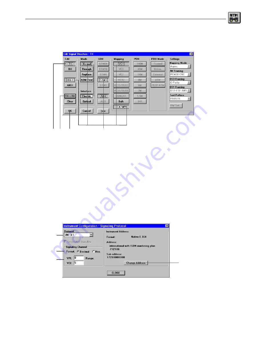
1. Click the toolbar icon or the “Edit - Signal Structure...” menu command
The “Edit Signal Structure” dialog window of the “Signal Structure” VI opens. The signal
structure is set column by column using the corresponding buttons.
Fig. A-10
The “Signal Structure” window and “Edit Signal Structure - TX” dialog
2. Click the “TX” button to configure the transmitting side.
3. Set the signal structure, e.g. “ITU-T”, “Normal”, “STM-1”, “AU4”, “VC4” and “ATM” by clicking
the appropriate buttons.
4. Click the “TX=>RX” button.
This sets the receiving side to the same settings as the transmitting side.
5. Confirm the input by clicking “OK”. this returns you to the “Instrument Configuration” dialog.
E) To configure the signaling
✓
The “Instrument Configuration” dialog is open.
1. Click the “SIG” button.
The “Instrument Configuration - Signaling Protocol” dialog window opens.
Fig. A-11
The “Instrument Configuration - Signaling Protocol” sub dialog
2. Select the required item, e.g. “Q.2931” in the “Protocol” list box.
3. Select the input format, e.g. “Decimal” using the option buttons.
4. Edit the VPI and VCI values in the entry boxes.
The available range is shown under “Range”.
2. 4.
3.
5.
2.
3.
4.
5.
Содержание ANT-20
Страница 8: ...Broadband Analyzer Generator ANT 20 ANT 20E vi Notes ...
Страница 64: ...Broadband Analyzer Generator ANT 20 ANT 20E O 46 Operation Notes ...
Страница 110: ...Broadband Analyzer Generator ANT 20 ANT 20E TB 16 Technical Background Notes ...
Страница 126: ...Broadband Analyzer Generator ANT 20 ANT 20E iv Notes ...


