


WM_PRJ_Q2400_PTS_005 -007
18th January 2006
Confidential©
All rights reserved
Page:
38
/
51
This document is the sole and exclusive property of WAVECOM. Not to be
distributed or divulged without prior written agreement.
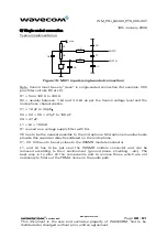
3 Radio design
3.1 Antenna characteristics
WAVECOM recommends to use an antenna with the following characteristics:
Q2406 Q2426
Characteristic
E-GSM 900
DCS 1800
GSM 850
PCS 1900
Frequency TX
880 to 915 MHz
1710 to 1785 MHz
824 to 849 MHz
1850 to 1910 MHz
Frequency RX
925 to 960 MHz
1805 to 1880 MHz
869 to 894 MHz
1930 to 1990 MHz
Impedance
50 ohms
Rx max
1.5 :1
VSWR
Tx max
1.5 :1
Typical
radiated gain
0 dBi in one direction at least
Frequency depends on application. A dual-Band antenna shall work in all these
frequency bands.
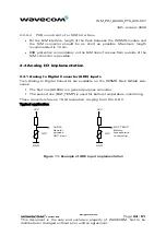
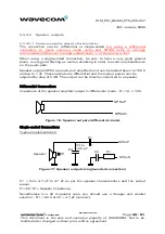
3.2 Antenna implementation
The impedance is 50
Ω
nominal and the DC impedance is 0
Ω
.
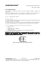
3.2.1 Recommendations
Antenna sub-system and integration in the application is a major issue.
Attention should be paid to:
•
the design of the antenna line on the application PCB,
•
the antenna connector (type + losses),
•
the antenna choice.
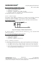
These elements could affect GSM performances such as sensitivity and emitted
power.
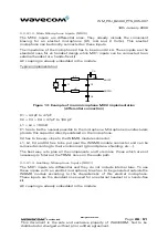
The antenna should be isolated as much as possible from the digital circuitry
(including the interface signals) it is strongly recommended to shield the
terminal.
On terminals including the antenna, a poor shielding could dramatically affect
the sensitivity of the terminal. Moreover, the power emitted through the antenna
could affect the application.