background image

Innovation Hot Water Hot Water Boiler User Manual 

- INTERNATIONAL


CHAPTER 8 – WATER HEATER MANAGEMENT 


OMM-0120_0A   


AERCO International, Inc. 

 100 Oritani Dr. 

  Blauvelt, NY 10913  


  Page 

123

 of


174


GF-128-I   

Phone: 800-526-0288


 11/15/2016


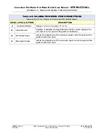
8.10  TROUBLESHOOTING 

Faults which may occur during WHM operation include the items listed in Table 8-3. 


Table 8-3.  WHM Troubleshooting 

FAULT INDICATION 

PROBABLE CAUSE 

CORRECTIVE ACTION 

OUTLET 
TEMPERATURE 
display is flashing on 2  
C- More Control Panels 

1. 

Two C-Mores have their 
WHM Mode menu option 
set to WHM Master 


1. 

Check the WHM Mode entries in 
the units which have their displays 
flashing. Change one of the WHM 
Mode settings to WHM Slave.


REMOTE

 LED on one 

or more WHM units is 
Off. 

1. 

Improperly connected or 
faulty RS485 Modbus 
wiring. 


2. 

Improper Comm address. 


3. 

Unit Comm address is 
not unique.


1. 

Check the polarity of the RS485 
Comm connections on the I/O 
board of the affected unit. Also, 
ensure that all Modbus wiring 
connections to the unit are secure.


2. 

Verify that the address of the 
affected unit is within the allowable 
range     (1 thru 8).


3. 

Check to ensure that none of the 
units have the same Comm 
address.


Actuator-controlled 
sequencing valve does 
not open 

1. 

Control cable not 
connected to valve 
actuator.


2. 

24 VAC power not being 
supplied to valve 
actuator. 


3. 

Defective valve actuator.


1. 

Ensure that the control cable from 
the unit’s I/O Box is connected to 
the valve actuator.


2. 

Remove the enclosure cover from 
the valve actuator and verify that 24 
VAC is present at Terminal 2 of the 
actuator.


3. 

Replace valve actuator. Following 
replacement, the actuator stroke 
will have to be calibrated to ensure 
it fully opening and closing. 


8.11  SEQUENCING VALVE DESCRIPTION & OPERATION 

Brief descriptions of Actuator-Controlled Sequencing Valve  (P/N 

92123

)  and its operating 

characteristics are provided in  sections 9.11.1 and 9.11.2, respectively. The installation of the 
valve itself is described in Chapter 2, section 2.5.1. 

8.11.1  Sequencing Valve Description 

The Actuator-Controlled Sequencing Valve shown in Figure 8-5 is comprised of the following 
main components: 

  2” Brass Ball Valve 

  Actuator Linkage 

  Actuator Housing 

  Valve Shaft Handle 


Содержание Aerco Innovation 800

Страница 1: ...and Maintenance INNOVATION Series Gas Fired Hot Water Boilers Natural Gas Modulating Condensing Hot Water Boiler Models Applicable to Serial Number G 16 2000 and above This guide applies to the follo...

Страница 2: ...DISCLAIMER The information contained in this manual is subject to change without notice from AERCO International Inc AERCO makes no warranty of any kind with respect to this material including but no...

Страница 3: ...RATURE RELIEF VALVE INSTALLATION 21 2 9 CONDENSATE DRAIN PIPING 22 2 10 GAS SUPPLY PIPING 24 2 10 1 Gas Supply Specifications 24 2 10 2 Manual Gas Shutoff Valve 24 2 10 3 External Gas Supply Regulator...

Страница 4: ...ply Manometer 50 4 2 3 Accessing the Analyzer Probe Port 51 4 2 4 Connecting Multimeter to Flame Detector 51 4 2 5 Recommendations for Temperature Calibration 52 4 2 6 Recommendations for WHM Water He...

Страница 5: ...ectrical Short Test 86 6 11 2 Low Water Cutoff LWCO Standard C More Test 88 6 12 SHUTTING THE HOT WATER BOILER DOWN FOR AN EXTENDED PERIOD OF TIME 88 6 13 PLACING THE HEATER BACK IN SERVICE AFTER A PR...

Страница 6: ...Sequencing Valve Description 123 8 11 2 Sequencing Valve Operating Characteristics 126 APPENDIX A INNOVATION MENU ITEM DESCRIPTIONS 127 Table A 1 Operating Menu Item Descriptions 127 Table A 2 Setup...

Страница 7: ...shed with each unit When the heater is ordered with a Sequencing Valve SV up to eight 8 Innovation Hot Water Boilers can be controlled by the WHM system utilizing RS485 Modbus protocol All available I...

Страница 8: ...events transmitted per second It is not equal to bits per second unless each symbol is 1 bit long BLDG Bldg Building BTU British Thermal Unit A unit of energy approximately equal to the heat required...

Страница 9: ...0 45 kg LED Light Emitting Diode LN Low Nitrogen Oxide MA mA Milliampere 1 thousandth of an ampere MAX Max Maximum MIN Min Minimum Modbus A serial half duplex data transmission protocol developed by...

Страница 10: ...point Temperature SHLD Shld Shield SPDT Single Pole Double Throw a type of switch SSD Slave to Slave programming SSOV Safety Shut Off Valve SV Sequencing Valve Used with Water Heater Management WHM sy...

Страница 11: ...ore installations are made IMPORTANT This Instruction Manual is an integral part of the product and must be maintained in legible condition It must be given to the user by the installer and kept in a...

Страница 12: ...soaps used for gas pipe leak testing are corrosive to metals The piping must be rinsed thoroughly with clean water after leak checks have been completed CAUTION DO NOT use this heater if any part has...

Страница 13: ...OLONGED SHUTDOWN After prolonged shutdown it is recommended that the startup procedures in Chapter 4 and the safety device test procedures in Chapter 6 of this manual be performed to verify all system...

Страница 14: ...Water Boiler User Manual INTERNATIONAL CHAPTER 1 SAFETY PRECAUTIONS Page 14 of 174 AERCO International Inc 100 Oritani Dr Blauvelt NY 10913 OMM 0120_0A 11 15 2016 Phone 800 526 0288 GF 128 I This Pag...

Страница 15: ...sign for the shipment Note the information on the carrier s paperwork and request a freight claim and inspection by a claims adjuster before proceeding Any other visual damage to the packaging materi...

Страница 16: ...sions required by AERCO are listed below However if Local Building Codes require additional clearances these codes shall supersede AERCO s requirements Minimum acceptable clearances required are as fo...

Страница 17: ...ccess to the lifting lugs Remove the four 4 lag screws securing the unit to the shipping skid Lift the unit off the shipping skid and position it on the 4 to 6 inch 10 2 to 15 2 cm housekeeping concre...

Страница 18: ...as pipe dope Do NOT use Teflon tape IMPORTANT If the Innovation Hot Water Boiler is equipped for use with the C More Water Heater Management WHM system then an actuator controlled ball valve will be...

Страница 19: ...ter inlet of the unit using the pipe union and nipple provided 3 Ensure that the valve is positioned with the actuator enclosure position as shown in Figure 2 3b 4 AERCO recommends that another pipe n...

Страница 20: ...nclosure at the rear of the unit In order to access this assembly the right rear middle panel must be removed Refer to Figure 2 5 This assembly contains a recirculation pump that connects the upper ho...

Страница 21: ...setpoint is 150 psig 1 034 kPa at 210 F 98 9 C A suitable pipe joint compound should be used on the threaded connections Any excess should be wiped off to avoid getting any into the valve body The re...

Страница 22: ...ed to ensure proper condensate drainage The condensate trap inlet Figure 2 7 must be level with or lower than the exhaust manifold drain port The base of the condensate trap must be supported to ensur...

Страница 23: ...hey look slightly different LEFT SIDE VIEW Figure 2 7 Sample Condensate Trap Installation NOTE As a general guideline AERCO recommends use of its Condensate Neutralizer Kit to raise the pH level of th...

Страница 24: ...must be supported from the floor ceiling or walls only and must not be supported by the unit A suitable piping compound approved for use with natural gas should be used Any excess must be wiped off to...

Страница 25: ...m to the unit A lock up style regulator MUST be used when gas supply pressure will exceed 14 W C 3 49 kPa For all installations that EXCEED 7 W C 1 74 kPa gas pressure a mandatory external gas supply...

Страница 26: ...ure 2 9 Power Box Location Partial Front View Front Panel Removed 2 11 1 Electrical Power Requirements The AERCO Innovation Heater accepts 220 VAC single phase 50 Hz less than 15A The Power Box contai...

Страница 27: ...is located on the upper left portion of the unit front panel Figure 2 11 behind the removable front panel door To access the I O Box terminal strips shown in Figure 2 11 loosen the four cover screws a...

Страница 28: ...The COMBUSTION AIR and AIR SENSOR COMMON terminals are not applicable to this unit 2 12 3 O2 SENSOR Terminals The O2 SENSOR and O2 SENSOR terminals are not currently used in this unit 2 12 4 SPARK SIG...

Страница 29: ...nals is provided 2 12 6 VALVE FEEDBACK Terminals The Valve Feedback terminals are used when the Sequencing Isolation Valve Feedback option is selected The Valve Feedback signal is connected to the Val...

Страница 30: ...s The unit offers two interlock circuits for interfacing with Energy Management Systems and auxiliary equipment such as pumps or louvers or other accessories These interlocks are called the Remote Int...

Страница 31: ...are rated for 120 VAC 5 amps Refer to Figure 2 12 to locate the AUX RELAY terminals N C COM N O for wiring connections 2 13 FLUE GAS VENT INSTALLATION AERCO Gas Fired Venting and Combustion Air Guide...

Страница 32: ...he protection and longevity of the equipment and warranty validation The more common methods of combustion air supply are outlined in the following sections For combustion air supply from ducting cons...

Страница 33: ...CAUTION All of the installation procedures in Chapter 2 must be completed before attempting to start the unit WARNING ELECTRICAL VOLTAGES IN THIS SYSTEM INCLUDE 220 110 AND 24 VOLTS AC IT MUST BE SERV...

Страница 34: ...er User Manual INTERNATIONAL CHAPTER 3 OPERATION Page 34 of 174 AERCO International Inc 100 Oritani Dr Blauvelt NY 10913 OMM 0120_0A 11 15 2016 Phone 800 526 0288 GF 128 I Figure 3 1 Control Panel Fro...

Страница 35: ...ng in the Deadband mode 3 VFD Display Vacuum Fluorescent Display VFD consists of 2 lines each capable of displaying up to 16 alphanumeric characters The information displayed includes Startup Messages...

Страница 36: ...pressed and the menu item is flashing pressing the arrow key will increment the selected setting DOWN Arrow When in one of the main menu categories Figure 3 2 pressing this key will select the displa...

Страница 37: ...3 1 Therefore it is imperative that you be thoroughly familiar with the following basic steps before attempting to perform specific menu procedures Menu Processing Procedure 1 The Control Panel will...

Страница 38: ...GF 128 I Figure 3 2 Menu Structure NOTE The following sections provide brief descriptions of the options contained in each menu Refer to Appendix A for detailed descriptions of each menu option Refer...

Страница 39: ...of Appendix A Innovation Menu Item Descriptions Table 3 2 Operating Menu Menu Item Display Available Choices or Limits Appears only if enabled in the following menu Minimum Maximum 1 Active Setpoint 4...

Страница 40: ...00 am 11 59 pm 4 Date 01 01 00 12 31 99 5 Unit of Temp Fahrenheit or Celsius Fahrenheit 6 Comm Address 0 127 0 7 Baud Rate 2400 4800 9600 19 2K 9600 8 OnAER Mode Ethernet or SD Card Ethernet 9 Upload...

Страница 41: ...A 1 5V 0 20 mA 0 5V PWM Input Legacy BMS Network 4 20 mA 1 5V 7 Outdoor Sensor Enabled or Disabled Disabled 8 System Start Tmp If Outdoor Sensor Enabled 30 F 1 1 C 100 F 37 8 C 60 F 15 5 C 9 Setpt Lo...

Страница 42: ...1 Prop Band 1 F 17 2 C 200 F 93 3 C 30 F 1 1 C 2 Integral Gain 0 00 10 00 3 00 3 Derivative Time 0 00 min 2 00 min 0 20 min 4 Warmup Prop Band 1 F 17 2 C 120 F 48 9 C 95 F 35 C 5 Warmup Int Gain 00 2...

Страница 43: ...30 26 Fdback Value 0 100 Read Only Value 27 Temp Gov Enable or Disable Enable 28 GOV Limit 5 0 100 30 29 GOV Limit 7 0 100 20 30 GOV Limit 10 0 100 15 31 GOV Limit 12 0 100 10 32 GOV Limit 15 0 100 5...

Страница 44: ...100 70 14 PWM In Adj 5 0 5 0 0 0 15 Analog In Adj 5 0 5 0 0 0 16 Flow In Adj 5 0 5 0 0 0 17 Supply Gas Pressure In Adj 5 0 5 0 0 0 18 Gas Plate dp In Adj 5 0 5 0 0 0 19 mA Out Adj 1 0 mA 1 0 mA 0 0 mA...

Страница 45: ...switches to ensure they are closed These switches include Safety Shut Off Valve Proof of Closure POC switch Low Water Level switch High Water Temperature switch High Gas Pressure switch Low Gas Press...

Страница 46: ...SSOV location Figure 3 3 SSOV Location Gas Train P N 22282 shown 3 With all required safety device switches closed a purge cycle will be initiated and the following events will occur a The Blower rela...

Страница 47: ...nition cycle and the following events occur a The Air Fuel Valve rotates to the low fire ignition position and closes the Ignition switch The dial on the Air Fuel Valve Figure 3 6 will read between 25...

Страница 48: ...osed STANDBY will be displayed 3 10 START STOP LEVELS The ignition position start and stop levels are the Air Fuel Valve positions open that start and stop the unit based on load These levels are Fact...

Страница 49: ...operate the unit safely and at a high thermal efficiency with low flue gas emissions Initial unit start up must be performed ONLY by AERCO factory trained start up and service personnel After performi...

Страница 50: ...s Tube of silicone adhesive 4 2 2 Installing Gas Supply Manometer The gas supply manometer is installed in the gas train as follows Installing Gas Supply Manometer 1 Close the main manual gas supply s...

Страница 51: ...1 Refer to Figure 4 2 and remove the 1 8 NPT plug from the rear of the exhaust manifold 2 If necessary adjust the stop on the combustion analyzer probe so it will extend mid way into the flue gas flow...

Страница 52: ...se water temperature faults poor water temperature control and rapid cycling of the heater 4 2 6 Recommendations for WHM Water Heater Management Operation In case of multiple Innovation units it is hi...

Страница 53: ...ter supply and return valves to the unit and ensure that the system pumps are running 2 Open the NATURAL GAS supply valve s to the unit 3 Set the control panel ON OFF switch to the OFF position 4 Turn...

Страница 54: ...re the oxygen O2 level carbon monoxide CO nitrogen oxide NOx and flame strength readings with the range shown in step 22 below You may need to adjust O2 above this range to meet ultra low NOx requirem...

Страница 55: ...bustion Calibration sheet Combustion Calibration Readings Valve Position Oxygen O2 Nitrogen Oxide NOx Carbon Monoxide CO Flame A INN 800 INN 1060 INN 1350 100 6 0 0 2 5 0 0 2 20 ppm 100 ppm 6 80 5 4 0...

Страница 56: ...hanged it must be done prior to temperature control calibration There are two primary adjustments for performing temperature calibration Min Load Adj and Max Load Adj minimum and maximum load adjustme...

Страница 57: ...stment 1 While monitoring the VALVE POSITION bar graph create a minimum load on the system that will yield a steady valve position between 25 and 35 NOTE It may be desirable to shut off the outlet val...

Страница 58: ...ow the unit s setpoint 4 If the outlet temperature is stabilized no adjustment is necessary If the temperature is not stabilized proceed to step 5 5 Press the MENU key and select the Tuning Menu 6 Pre...

Страница 59: ...t adjustable and is permanently fixed at 190 F 87 7 C This switch will shut down and lock out the heater if the water temperature exceeds 190 F 87 7 C Following an over temperature condition it must b...

Страница 60: ...t Water Boiler User Manual INTERNATIONAL CHAPTER 4 INITIAL START UP Page 60 of 174 AERCO International Inc 100 Oritani Dr Blauvelt NY 10913 OMM 0120_0A 11 15 2016 Phone 800 526 0288 GF 128 I This Page...

Страница 61: ...de 220 110 and 24 volts AC Power must be removed prior to performing wire removal or other test procedures that can result in electrical shock 5 2 LOW GAS PRESSURE FAULT TEST To simulate a low gas pre...

Страница 62: ...nit in Manual mode at a valve position firing rate of 25 5 Slowly increase the gas pressure using the adjustment screw on the SSOV 6 The unit should shut down and display a HIGH GAS PRESSURE fault mes...

Страница 63: ...n the water supply shut off valve to the unit to refill 10 After the shell is full press the LOW WATER LEVEL RESET button to reset the low water cutoff 11 Press the CLEAR button to reset the FAULT LED...

Страница 64: ...cks are shipped from the factory jumpered closed However each of these interlocks may be utilized in the field as a remote stop and start an emergency cut off or to prove that a device such as a pump...

Страница 65: ...cur during ignition or while the unit is already running To simulate each of these fault conditions proceed as follows Flame Fault Tests 1 Set the ON OFF switch to the OFF position 2 Place the unit in...

Страница 66: ...ck the operation of the Blower Proof switch and Blocked Inlet switch shown in Figure 5 4 Air Flow Fault Tests 1 Disable the blower output drive voltage as follows a Press the MENU key until CONFIGURAT...

Страница 67: ...urn off the blower by going to the Configuration Menu Analog Output menu item and select OFF 7 The Blower Proof switch will open and the blower should stop The unit should shut down and display AIRFLO...

Страница 68: ...in Manual mode and set the valve position between 25 and 30 3 Refer to Figure 5 1 and locate the SSOV 4 Remove the cover from the SSOV by loosening the screw shown in Figure 5 6 Lift off the cover to...

Страница 69: ...7 3 Remove one of the two wires 171 or 172 from the Purge switch Figure 5 8 4 Initiate a unit start sequence 5 The unit should begin its start sequence then shut down and display PRG SWITCH OPEN DURI...

Страница 70: ...shut down and display IGN SWITCH OPEN DURING IGNITION 7 Replace the wire on the Ignition switch and press the CLEAR button The unit should restart Figure 5 7 Typical Air Fuel Valve Cover Location Figu...

Страница 71: ...OBSERVED DISCONNECT THE AC SUPPLY BY TURNING OFF THE SERVICE SWITCH AND AC SUPPLY CIRCUIT BREAKER SHUT OFF THE GAS SUPPLY AT THE MANUAL SHUT OFF VALVE PROVIDED WITH THE UNIT ALLOW THE UNIT TO COOL TO...

Страница 72: ...OFF position Disconnect AC power from the unit 2 Remove the side and rear panels from the unit 3 Disconnect the ignition cable and ground wire from the igniter injector 4 Refer to Figure 6 1 Disconne...

Страница 73: ...toward the intake manifold perimeter 8 Refer to Figure 6 2 and reinstall the igniter injector on the intake manifold flange Install one to three clocking washers as needed to position the igniter inj...

Страница 74: ...oth 7 Reinstall the flame detector and flame detector gasket 8 Reconnect the flame detector lead wire 9 Reinstall the side and rear panels on the unit 6 4 COMBUSTION CALIBRATION Combustion settings mu...

Страница 75: ...t manifold and vent connector and remove all sealant from both surfaces in preparation for reassembly 3 Remove the side and rear panels from the unit Also remove the bottom panel of the cabinet to exp...

Страница 76: ...ifold 12 Carefully lower and remove the intake manifold burner assembly the two burner gaskets P N GP 18899 and the intake manifold flange gasket P N 81198 See Figures 6 3 and 6 4 13 Disconnect the ex...

Страница 77: ...nspection Continued Figure 6 4 Intake Manifold and Burner PARTIAL RIGHT SIDE VIEW WITH SUPPORT REMOVED Figure 6 5 Intake and Exhaust Manifolds EXHAUST MANIFOLD 5 16 18 STUDS 6 SIDE NUTS 2 FRONT NUT 1...

Страница 78: ...ved in step 15 19 When attaching the intake manifold to the exhaust manifold removed in step 11 torque the six 5 16 hex nuts to 12 ft lbs WARNING The manifold to heat exchanger gasket must be held in...

Страница 79: ...surfaces thoroughly before reassembling the upper head AERCO recommends that NEW gaskets be used when reassembling 7 Place two Baffle Spacer strips P N 49274 included with kit 24427 TAB on top of the...

Страница 80: ...and lets the hot water boiler continue to perform at its peak efficiency low water heating cost In addition to reduced inspection frequency the periodic maintenance to remove and flush the hot water...

Страница 81: ...els hold approximately the gallons of water listed below INN800 24 5 gallons 92 7 L drain at least 12 25 gallons 46 37 L INN1060 23 gallons 87 01 L drain at least 11 5 gallons 43 53 L INN1350 20 6 gal...

Страница 82: ...circulation period based on the time in service and water hardness When the foaming action stops HydroSkrub strength is depleted two pounds of deposits removed per gallon used or the equipment is fre...

Страница 83: ...and bubbling indicates the solution is still active Little or no reaction indicates that the solution is expended This test should be performed near the end of the circulating time If the solution has...

Страница 84: ...isconnect the external condensate trap by loosening and then removing connections on the inlet and outlet sides of the condensate trap see Figure 6 9 2 Loosen the four 4 thumbscrews securing the trap...

Страница 85: ...nel to the OFF position Disconnect AC power from the unit 2 Remove the side panels from the unit 3 Refer to Figure 6 10 and locate the air filter attached to the air fuel valve inlet 4 Using a flat ti...

Страница 86: ...rm the standard Low Water Cutoff test using the C More controls On the Innovation series the LWCO probe is located on the heat exchanger body on the left side of the unit Refer to Figure 6 11 for an i...

Страница 87: ...ure 6 12 Figure 6 12 Removing Shell Harness Cable from P5 Conn on C More Rear Panel 3 Using an ohmmeter connect one ohmmeter probe to the LWCO capacitor terminal on the unit shell as shown on left in...

Страница 88: ...re controls as described below Standard Low Water Cutoff C More Test 1 Turn on the AC power to the unit 2 Press the TEST switch on the C More controller and confirm that the blinking Low Water Level m...

Страница 89: ...nitor P N 61034 evaluates the strength of the current between the ignition transformer and igniter or igniter injector Wire 140 connected to the ignition transformer see Figure 6 14 passes through the...

Страница 90: ...Hot Water Boiler User Manual INTERNATIONAL CHAPTER 6 MAINTENANCE Page 90 of 174 AERCO International Inc 100 Oritani Dr Blauvelt NY 10913 OMM 0120_0A 11 15 2016 Phone 800 526 0288 GF 128 I This Page Is...

Страница 91: ...to isolate and correct the fault General Troubleshooting Instructions 1 Observe the fault messages displayed in the Control Box display 2 Refer to the Fault Indication column in Troubleshooting Table...

Страница 92: ...ater Boiler User Manual INTERNATIONAL CHAPTER 7 TROUBLESHOOTING GUIDE Page 92 of 174 AERCO International Inc 100 Oritani Dr Blauvelt NY 10913 OMM 0120_0A 11 15 2016 Phone 800 526 0288 GF 128 I This Pa...

Страница 93: ...the Blower Proof switch and inspect for signs of blockage clean or replace as necessary 4 Remove the Blocked Air Inlet switch and inspect for signs of blockage clean or replace as necessary 5 Measure...

Страница 94: ...combustion blower for signs of blockage 5 Measure for 24 VAC during start sequence from each side of the switch to ground If 24VAC is not present refer to qualified service personnel 6 See CORRECTIVE...

Страница 95: ...lled or loose 2 Worn flame detector 3 No spark from Spark Plug 4 Defective Ignition Transformer 5 Defective Ignition Stepper IGST Board 6 Defective SSOV 7 Carbon or other debris on Burner 1 Inspect an...

Страница 96: ...in condensate drain HEAT DEMAND FAILURE 1 The Heat Demand Relays on the Ignition Stepper board failed to activate when commanded 2 Relay is activated when not in Demand 1 Press CLEAR button and restar...

Страница 97: ...nt of unit and setpoint of Temperature switch Ensure that the temperature switch is set higher than the unit s setpoint 6 If the system is a variable flow system monitor system flow changes to ensure...

Страница 98: ...nition position towards closed during the ignition cycle If the valve does not rotate back to the ignition position check the Air Fuel Valve calibration If calibration is okay the problem may be in th...

Страница 99: ...e water level circuitry 3 Defective water level probe 1 Check system for sufficient water level 2 Test water level circuitry using the Control Box front panel LOW WATER TEST and RESET buttons Replace...

Страница 100: ...to ensure that the switch is wired correctly correct wire numbers on the normally open terminals 4 Check DS1 DS2 LEDs on Power Supply Board If they are not steady ON replace Power Supply Board 5 Chec...

Страница 101: ...fault persists replace actuator SSOV RELAY FAILURE 1 SSOV relay failed on IGST board 2 Floating Neutral 3 Hot and Neutral reversed at SSOV 1 Press CLEAR button and restart unit If fault persists repla...

Страница 102: ...properly from 0 fully closed to 100 fully open positions Verify VALVE POSITION bargraph and dial on the Air Fuel Valve track each other to indicate proper operation If operation is not correct perform...

Страница 103: ...ccur without a specific fault message being displayed TABLE 7 2 HOT WATER BOILER TROUBLESHOOTING WITH NO FAULT MESSAGE DISPLAYED OBSERVED INCIDENT PROBABLE CAUSES CORRECTIVE ACTION Fluctuating Gas Pre...

Страница 104: ...ater Boiler User Manual INTERNATIONAL CHAPTER 7 TROUBLESHOOTING GUIDE Page 104 of 174 AERCO International Inc 100 Oritani Dr Blauvelt NY 10913 OMM 0120_0A 11 15 2016 Phone 800 526 0288 GF 128 I This P...

Страница 105: ...16 Figure 7 1 Gas Train Component Locations Figure 7 2 Intake Manifold Shown removed from Heater SSOV TO AIR FUEL VALVE LOW GAS PRESSURE SWITCH HIGH GAS PRESSURE SWITCH FLAME DETECTOR INTAKE MANIFOLD...

Страница 106: ...of 174 AERCO International Inc 100 Oritani Dr Blauvelt NY 10913 OMM 0120_0A 11 15 2016 Phone 800 526 0288 GF 128 I Figure 7 3 SSOV Actuator With Gas Pressure Adjustment SSOV ACTUATOR COVER ACTUATOR CO...

Страница 107: ...can control up to eight 8 hot water boilers in parallel Each hot water boiler controlled by the WHM must be equipped with an Actuator Controlled Sequencing Valve P N 92123 These valves are installed o...

Страница 108: ...operating time for each unit on the system and attempts to balance the system so that all units operate for approximately the same number of hours 8 3 NEW AERCO WHM FEATURES 8 3 1 Valve Feedback The V...

Страница 109: ...k of the C More box and insert the dongle in its place 3 In the Cal Temp Sensor item of the calibration menu change the menu entry to Start and hit the Enter Key 4 This feature will only calibrate Inl...

Страница 110: ...events the Outlet Temperature from exceeding the High Temp Limit The High Temperature Governor is independent of the system PID and Feed forward control methodology and independently modulates the Val...

Страница 111: ...t ignite Wtr Heatr Active This Slave unit is active its valve is opened and it can ignite REMOTE SIG FAULT Remote signal fault WHMS FAILSAFE WHMS is in Failsafe Mode Example If all available heaters...

Страница 112: ...0 F 54 4 C 9 Setback Start 12 00am 11 59pm 12 00am 10 Setback End 12 00am 11 59pm 12 00am 11 WHM Auto Mstr Yes or No No 12 WHM Auto Timer 10 sec 120 sec 30 sec 13 WHM min addr 1 8 1 14 WHM max addr 1...

Страница 113: ...character for each unit Default 0 0 Off 1 On Off Line Not available fault etc A Lead On B Lag On a Lead Off b Lag Off NOTE The Level 2 Password 6817 in the Setup Menu must be entered to view or chang...

Страница 114: ...be a reasonable spread between the 2 values 5 Lead Lag Hours This menu option is designed to spread the total number of run hours accumulated on all units in the system so that each unit has approxim...

Страница 115: ...tatus 8 Displays the valve status of all the units 0 valve closed 1 valve open 2 valve stuck closed 3 valve stuck open 18 1 Comm Errors 8 Display Comm Errors of all the units 19 20 WHM On Delay WHM of...

Страница 116: ...dback Enable or disable the Valve feedback feature 28 Valve Fdbk timer The time allotted the Valve to Open or Close once a command has been issued before invoking a fault 29 ValveFdbk Status Displays...

Страница 117: ...instructions for implementing a Water Heater Management System WHM to control up to eight 8 AERCO Innovation Hot Water Boilers Some of the descriptions and procedures included in Chapter 2 are repeat...

Страница 118: ...ng valve from its stowed location 2 Refer to Figure 8 2 and attach the valve to the cold water inlet of the unit shown in Figure 8 2 below using the pipe union and nipple provided 3 Ensure that the va...

Страница 119: ...The Modbus wiring connections are made at the RS485 COMM terminals on the I O board included with each C more Control System Connect the Modbus wiring as follows Modbus Network Wiring 1 Starting at t...

Страница 120: ...ished by simply ensuring that the 4 pin Molex connectors on the units are connected to the corresponding connectors on the valves Figure 8 4 WHMS Network Wiring Diagram NOTES Wiring to be shielded twi...

Страница 121: ...ntry Note that the Outlet Temperature display on the WHM Master will begin flashing every two seconds 6 Select the WHM Setpoint option If you want to change the current setpoint for WHM press the CHAN...

Страница 122: ...options are WHM Auto Mstr and WHM Auto Timer In order to view or change these two options the Level 2 Password 6817 must be entered as follows a Press the MENU key on the front panel of the C More and...

Страница 123: ...re 2 Verify that the address of the affected unit is within the allowable range 1 thru 8 3 Check to ensure that none of the units have the same Comm address Actuator controlled sequencing valve does n...

Страница 124: ...cing Valve P N 92123 The Actuator Housing contains a cover which is removed by simply loosening a single captive screw Removing the cover provides access to a PC Board containing wiring connections an...

Страница 125: ...ch Failure to observe this precaution may damage the Actuator The PC board also contains a brass button which is used to disengage the clutch and permit the ball valve to be manually rotated To diseng...

Страница 126: ...e Power Box of the Innovation Hot Water Boiler The 24 VAC power output and a 2 to 10 VDC control signal from the I O Box of the Hot Water Boiler are routed to the Sequencing Valve via a 4 pin Molex co...

Страница 127: ...Displays Inlet Water Temperature 3 Air Temp For monitoring purposes only 4 Outdoor Temp Displayed only if outdoor sensor is installed and enabled 5 Valve Position In Desired input valve position This...

Страница 128: ...am to 11 59 pm 4 Date Displays dates from 01 01 00 to 12 31 99 5 Unit of Temp Permits selection of temperature displays in degrees Fahrenheit F or degrees Celsius C 6 Comm Address For RS 485 communic...

Страница 129: ...unit shuts down 9 Setpoint Lo Limit Used to set the minimum allowable setpoint 40 F 4 4 C to Setpoint Hi Limit 10 Setpoint Hi Limit Used to set the maximum allowable setpoint Setpoint Lo Limit to 190...

Страница 130: ...low the Active Setpoint Demand Offset In addition the heater will fire at the 29 Valve Position level or below for a period of one minute When this entry is set to zero the unit will turn on again as...

Страница 131: ...etpoint error This is the time that this action advances the output Warmup The feature embodied in the next three menu items eliminates Temperature Overshoots during the Warmup period of a cold igniti...

Страница 132: ...Limit 7 When the Outlet Temperature exceeds the HIGH TEMPERATURE LIMIT 7 the effective Fire Rate will be reduced by the value entered in GOV Limit 7 30 GOV Limit 10 When the Outlet Temperature exceed...

Страница 133: ...sition Fire Rate increase rate when raising the Valve Position VP Up Rate is defined as Seconds per Step 11 VP Down Rate Allows adjustment of the Valve Position Fire Rate decrease rate when lowering t...

Страница 134: ...g from the presently set Stop Level to a maximum of 40 SKIP FEATURE Items 29 31 embody a feature that allows the user to define a Fire Zone the C More will avoid In the rare instance when a unit emits...

Страница 135: ...ion 3 8 for a range of choices and the default values MENU LEVEL OPTION DESCRIPTION 41 Outlet Wtr Offset Range 20 to 20 either F or C 42 Spark Monitor Enables or disables the Spark Monitor function wh...

Страница 136: ...iler User Manual INTERNATIONAL APPENDIX A INNOVATION MENU ITEM DESCRIPTIONS Page 136 of 174 AERCO International Inc 100 Oritani Dr Blauvelt NY 10913 OMM 0120_0A 11 15 2016 Phone 800 526 0288 GF 128 I...

Страница 137: ...and date that the unit was disabled FLAME PROVEN Displayed after flame has been detected for a period of 2 seconds Initially the flame strength is shown in After 5 seconds has elapsed the time and dat...

Страница 138: ...NG RUN The Flame signal was lost during run HEAT DEMAND FAILURE The Heat Demand Relays on the Ignition board failed to activate when commanded HIGH EXHAUST TEMPERATURE The High Exhaust Temperature Lim...

Страница 139: ...witch on the Air Fuel Valve opened during purge RECIRC PUMP FAILURE Internal Recirculation Pump has failed REMOTE SETPT SIGNAL FAULT The Remote Setpoint signal is not present or is out of range RESIDU...

Страница 140: ...iler User Manual INTERNATIONAL APPENDIX B STARTUP STATUS AND FAULT MESSAGES Page 140 of 174 AERCO International Inc 100 Oritani Dr Blauvelt NY 10913 OMM 0120_0A 11 15 2016 Phone 800 526 0288 GF 128 I...

Страница 141: ...0 60 70 80 90 100 110 120 130 140 150 160 170 180 190 200 210 220 230 240 250 40 34 4 28 9 23 3 17 2 12 2 6 7 1 1 4 4 10 15 5 21 1 26 7 32 2 37 8 43 3 48 9 54 4 60 65 6 71 1 76 7 82 2 87 8 93 3 98 9 1...

Страница 142: ...User Manual INTERNATIONAL APPENDIX C TEMPERATURE SENSOR RESISTANCE VOLTAGE CHART Page 142 of 174 AERCO International Inc 100 Oritani Dr Blauvelt NY 10913 OMM 0120_0A 11 15 2016 Phone 800 526 0288 GF 1...

Страница 143: ...NATIONAL APPENDIX D DIMENSIONAL DRAWINGS OMM 0120_0A AERCO International Inc 100 Oritani Dr Blauvelt NY 10913 Page 143 of 174 GF 128 I Phone 800 526 0288 11 15 2016 APPENDIX D DIMENSIONAL DRAWINGS Dra...

Страница 144: ...ser Manual INTERNATIONAL APPENDIX D DIMENSIONAL DRAWINGS Page 144 of 174 AERCO International Inc 100 Oritani Dr Blauvelt NY 10913 OMM 0120_0A 11 15 2016 Phone 800 526 0288 GF 128 I Drawing Number AP A...

Страница 145: ...SYSTEM BLOWER A F VALVE ACCESS 51 1 63079 HARNESS INNOVATION CONTROL 10 1 58039 BLOWER REPLACEMENT KIT AMETEK 8 9 52 1 69158 I O BOX WITH ONAER with SEQ VALVE 11 1 24311 3 A F VALVE ASSY INN 800 1060...

Страница 146: ...OWER FRU KIT 1 24111 BLOWER AMETEK 8 9 1 81064 GASKET BLOWER 1 81057 BLOWER INLET GASKET 1 88004 O RING 1 81160 GASKET BLOWER AMETEK 8 9 69126 LWCO CAPACITOR ASSEMBLY KIT 1 122843 LOW WATER CUT OFF 1...

Страница 147: ...INGS OMM 0120_0A AERCO International Inc 100 Oritani Dr Blauvelt NY 10913 Page 147 of 174 GF 128 I Phone 800 526 0288 11 15 2016 INN 1350 PICTURED INN 800 1060 PICTURED AERCO International Inc Blauvel...

Страница 148: ...INGS Page 148 of 174 AERCO International Inc 100 Oritani Dr Blauvelt NY 10913 OMM 0120_0A 11 15 2016 Phone 800 526 0288 GF 128 I LEFT REAR VIEW RIGHT FRONT VIEW LEFT SIDE VIEW PARTIAL FRONT VIEW AERCO...

Страница 149: ...ESSURE SWITCH 2 6 W C FALL N O 20 2 95029 FLANGE SSOV 1 1 2 NPT 3 1 60020 2 SWITCH ASSEMBLY GAS PRESSURE 2 20 W C 22 1 69005 ACTUATOR SSOV W REGULATOR 5 1 123542 FLANGE 2 125 2 NPT 23 1 69038 ACTUATOR...

Страница 150: ...GAS PRESSURE SWITCH 3 6 W C 17 2 95029 FLANGE SSOV 1 1 2 NPT 4 1 61002 12 HIGH GAS PRESSURE SWITCH 4 7 W C 19 1 69005 ACTUATOR SSOV W REGULATOR 5 1 123542 FLANGE 2 125 2 NPT 20 1 69038 ACTUATOR SSOV...

Страница 151: ...A x FEM 1 NPT 150 M I 2 1 61002 1 PRESSURE SWITCH 2 6 W C FALL N O 18 2 92036 VALVE SSOV 1 NPT 3 1 60020 2 SWITCH ASSEMBLY GAS PRESSURE 2 20 W C 20 1 69005 ACTUATOR SSOV W REGULATOR 5 1 123542 FLANGE...

Страница 152: ...VALVE ASSY 2 1 44108 BLOWER A F VALVE ADAPTER 13 3 9 21 PLUG HEX 1 8 NPT 3 1 81160 GASKET BLOWER 14 1 61002 5 BLOCKED INLET SWITCH 8 0 W C 4 1 24111 BLOWER AMETEK 8 9 15 1 60011 4 SWITCH ASSY BLOWER...

Страница 153: ...SSY 2 1 81160 GASKET BLOWER 11 1 59138 AIR FILTER 6 15 2 cm 3 1 24111 BLOWER AMETEK 8 9 12 1 61024 AIR INLET TEMPERATURE SENSOR 5 1 88004 O RING 2 244 BUNA N 16 1 60011 4 SWITCH ASSY BLOWER PROOF 6 1...

Страница 154: ...ETECTOR GASKET 15 8 54117 SCREW PAN HEAD 1 4 28 5 1 66037 FLAME DETECTOR 6 2 93358 PLUG 1 4 NPT HEX HD PIPE 7 1 GP 18899 BURNER FLANGE GASKET 8 2 52037 STUD 10 32 9 2 59027 STANDOFF THREADED 10 32 10...

Страница 155: ...r User Manual INTERNATIONAL APPENDIX F PIPING DRAWINGS OMM 0120_0A AERCO International Inc 100 Oritani Dr Blauvelt NY 10913 Page 155 of 174 GF 128 I Phone 800 526 0288 11 15 2016 APPENDIX F PIPING DRA...

Страница 156: ...ot Water Boiler User Manual INTERNATIONAL APPENDIX F PIPING DRAWINGS Page 156 of 174 AERCO International Inc 100 Oritani Dr Blauvelt NY 10913 OMM 0120_0A 11 15 2016 Phone 800 526 0288 GF 128 I Drawing...

Страница 157: ...ot Water Boiler User Manual INTERNATIONAL APPENDIX F PIPING DRAWINGS OMM 0120_0A AERCO International Inc 100 Oritani Dr Blauvelt NY 10913 Page 157 of 174 GF 128 I Phone 800 526 0288 11 15 2016 Drawing...

Страница 158: ...ot Water Boiler User Manual INTERNATIONAL APPENDIX F PIPING DRAWINGS Page 158 of 174 AERCO International Inc 100 Oritani Dr Blauvelt NY 10913 OMM 0120_0A 11 15 2016 Phone 800 526 0288 GF 128 I Drawing...

Страница 159: ...ot Water Boiler User Manual INTERNATIONAL APPENDIX F PIPING DRAWINGS OMM 0120_0A AERCO International Inc 100 Oritani Dr Blauvelt NY 10913 Page 159 of 174 GF 128 I Phone 800 526 0288 11 15 2016 Drawing...

Страница 160: ...ot Water Boiler User Manual INTERNATIONAL APPENDIX F PIPING DRAWINGS Page 160 of 174 AERCO International Inc 100 Oritani Dr Blauvelt NY 10913 OMM 0120_0A 11 15 2016 Phone 800 526 0288 GF 128 I Drawing...

Страница 161: ...ot Water Boiler User Manual INTERNATIONAL APPENDIX F PIPING DRAWINGS OMM 0120_0A AERCO International Inc 100 Oritani Dr Blauvelt NY 10913 Page 161 of 174 GF 128 I Phone 800 526 0288 11 15 2016 Drawing...

Страница 162: ...ot Water Boiler User Manual INTERNATIONAL APPENDIX F PIPING DRAWINGS Page 162 of 174 AERCO International Inc 100 Oritani Dr Blauvelt NY 10913 OMM 0120_0A 11 15 2016 Phone 800 526 0288 GF 128 I Drawing...

Страница 163: ...ot Water Boiler User Manual INTERNATIONAL APPENDIX F PIPING DRAWINGS OMM 0120_0A AERCO International Inc 100 Oritani Dr Blauvelt NY 10913 Page 163 of 174 GF 128 I Phone 800 526 0288 11 15 2016 Drawing...

Страница 164: ...ot Water Boiler User Manual INTERNATIONAL APPENDIX F PIPING DRAWINGS Page 164 of 174 AERCO International Inc 100 Oritani Dr Blauvelt NY 10913 OMM 0120_0A 11 15 2016 Phone 800 526 0288 GF 128 I Drawing...

Страница 165: ...L VIEWS Figure G 1 Control Panel Exploded View ENCLOSURE P N 124951 POWER SUPPLY BOARD P N 124362 IGNITION STEPPER BOARD P N 124361 FISH PAPER INSULATOR P N 124960 V F D DISPLAY MODULE P N 124527 FRON...

Страница 166: ...velt NY 10913 OMM 0120_0A 11 15 2016 Phone 800 526 0288 GF 128 I Figure G 2 C MORE CONTROL PANEL REAR VIEW SENSOR HARNESS CONNECTOR 7 PIN A F VALVE HARNESS CONNECTOR 16 PIN EXT SENSOR COMM HARNESS CON...

Страница 167: ...l INTERNATIONAL APPENDIX H C MORE WIRING DIAGRAMS OMM 0120_0A AERCO International Inc 100 Oritani Dr Blauvelt NY 10913 Page 167 of 174 GF 128 I Phone 800 526 0288 11 15 2016 APPENDIX H C MORE WIRING D...

Страница 168: ...ter Boiler User Manual INTERNATIONAL APPENDIX H C MORE WIRING DIAGRAMS Page 168 of 174 AERCO International Inc 100 Oritani Dr Blauvelt NY 10913 OMM 0120_0A 11 15 2016 Phone 800 526 0288 GF 128 I This...

Страница 169: ...Boiler User Manual INTERNATIONAL APPENDIX H C MORE WIRING DIAGRAMS OMM 0120_0A AERCO International Inc 100 Oritani Dr Blauvelt NY 10913 Page 169 of 174 GF 128 I Phone 800 526 0288 11 15 2016 Drawing N...

Страница 170: ...ter Boiler User Manual INTERNATIONAL APPENDIX H C MORE WIRING DIAGRAMS Page 170 of 174 AERCO International Inc 100 Oritani Dr Blauvelt NY 10913 OMM 0120_0A 11 15 2016 Phone 800 526 0288 GF 128 I This...

Страница 171: ...er Exhaust 123449 Three per unit Flame Detector Kit 24356 2 One kit per unit Igniter Kit 58023 One kit per unit Table I 2 Spare Parts Recommended for Maintenance DESCRIPTION PART NO QUANTITY Annual Ma...

Страница 172: ...Water Boiler User Manual INTERNATIONAL APPENDIX I RECOMMENDED SPARES Page 172 of 174 AERCO International Inc 100 Oritani Dr Blauvelt NY 10913 OMM 0120_0A 11 15 2016 Phone 800 526 0288 GF 128 I This Pa...

Страница 173: ...ondensate corrosion thermal stress failure mechanical defects or workmanship Operation of the heater using contaminated air will void the warranty The heat exchangers combustion chamber shall not be w...

Страница 174: ...or any of the above reasons within the specified time period from the date of original shipment s AERCO shall at its option modify repair or exchange the defective item AERCO shall have the option of...

Отзывы: