


Benchmark 750-3000 Installation & Startup Manual
SECTION 5
– SAFETY DEVICE TESTING
OMM-115_D
•
GF-200
•
5/9/2019
Technical Support
•
(800) 526-0288
•
Mon-Fri, 8 am - 5 pm EST Page 94 of
126
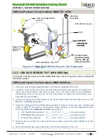
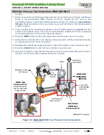
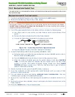
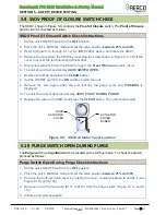
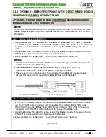
5.9 SSOV PROOF OF CLOSURE SWITCH CHECK
The SSOV, shown in Figure 5-9, contains the
Proof of Closure
switch. The
Proof of Closure
switch circuit is checked as follows:
SSOV Proof Of Closure Switch Check Instructions
1.
Set the unit’s ON/OFF switch to the
OFF
position.
2. Place the unit in MANUAL mode and set the valve position
between 25% and 30%
.
3. Refer to Figure 5-1a through 5-1c or 5-2 (BMK 3000), above, and locate the SSOV.
4. Remove the cover from the SSOV by loosening the screw shown in Figure 5-9. Lift off the
cover to access the terminal wiring connections.
5.
Disconnect wire #148 from the SSOV to “open” the
Proof Of Closure
switch circuit.
6. The unit should fault and display
SSOV SWITCH OPEN.
7. Replace wire #148 and press the
CLEAR
button.
8. Set the ON/OFF
switch to the
ON
position to start the unit.
9. Remove the wire again when the unit reaches the purge cycle and
PURGING
is
displayed.
10. The unit should shut down and display
SSOV FAULT DURING PURGE.
11. Replace the wire on the SSOV and press the
CLEAR
button. The unit should restart.
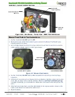
Figure 5-9: SSOV Actuator Cover Location
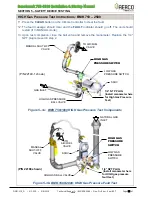
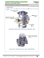
5.10 PURGE SWITCH OPEN DURING PURGE
The
Purge
switch (and
Ignition
switch) is located on the Air/Fuel Valve. To check the switch,
proceed as follows:
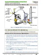
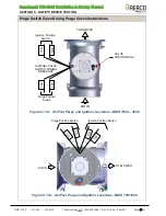
Purge Switch Open During Purge Check Instructions
1.
Set the unit’s ON/OFF switch to the
OFF
position.
2. Place the unit in MANUAL mode and set the valve position
between 25% and 30%
.
3. Remove the Air/Fuel Valve cover by rotating the cover counterclockwise to unlock it (see
Figure 5-10a and 5-10b).
4. Remove one of the two wires (#171 or #172) from the Purge switch (Figure 5-11a and 5-
11b).
5. Initiate a unit start sequence.
SSOV
ACTUATOR
COVER
ACTUATOR
COVER
SCREW