


Document #10-32813 Rev A; June 07, 2019
Page
10
of 69
Chassis Mount
With no DIN rail, mount the removable backplane to a panel using a #8 3/4 screw, no washers of any kind, and torque to
10-15 lbs. This illustrates the backplane dimensions and screw position of three modules mounted side by side.
Figure 3: Back Plane Dimensions (illustrating 3 connected units)
Wiring Power and Communications
The RMA PLUS module can be installed as a stand-alone module or interconnected with other RM modules on the DIN
rail via the standard EZ-ZONE modular interconnection point.
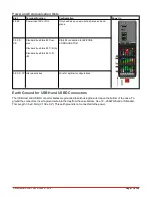
Slot C Power and Communications
Slot C on the bottom rear of the device provides connections for power, standard bus, and inter-module bus com-
munications.
Low Power Input Requirements (same for all RM models)
l
20.4 to 30.8 VAC ~(ac)/ m (dc) 14VA
l
47 to 63Hz
l
Controller module power consumption: 7 watts maximum
l
31 Watts maximum power for power supply part # 0847-0299-0000
l
60 Watts maximum power for power supply part # 0847-0300-0000
l
91 Watts maximum power for power supply part # 0847-0301-0000
l
Class 2 or safety extra low voltage (SELV) power source required to comply with UL® standards


