Watlow Anafaze PPC-2000 Скачать руководство пользователя страница 53

PPC-2000 User’s Guide

Chapter 2: Hardware Installation

Doc.# 30002-00 Rev 2.3

Watlow Anafaze

29

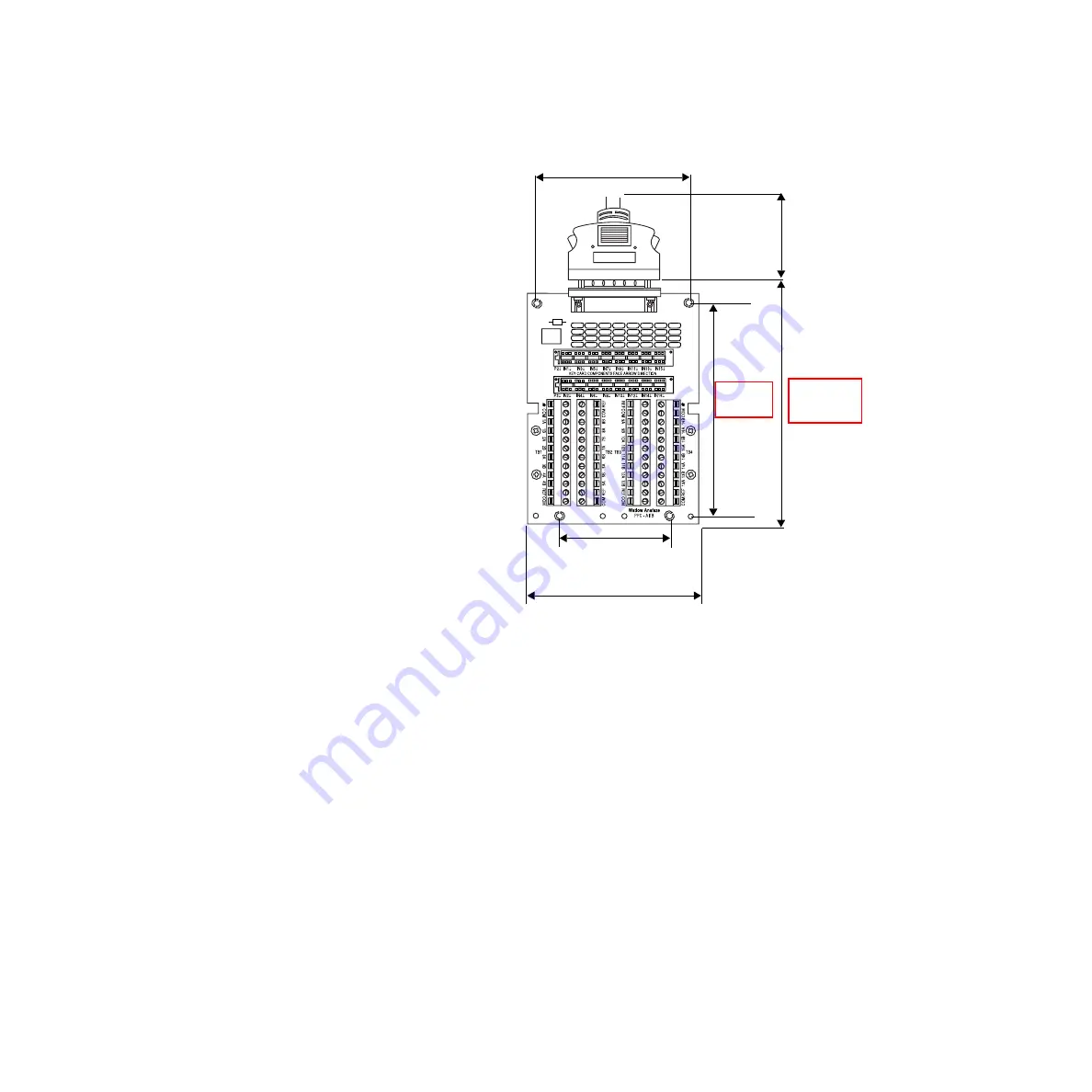
For more detailed specification information, refer to

 Chapter 7, 

Specifications

.

Figure 2.13 AITB Dimensions / Clearances

2.6"

4.0" W

4.70"

5.10" L

2.0"

3.6" 
(91 mm)

(51 mm)

(130 mm)

(119 mm)

(102 mm)

(66 mm)

5.756"
(146 mm)

5.1"
(128 mm)

Содержание Anafaze PPC-2000

Страница 1: ...PPC 2000 User s Guide WATLOW 1241 Bundy Boulevard Winona Minnesota USA 55987 Phone 1 507 454 5300 Fax 1 507 452 4507 Part No 0600 3000 2000 Rev 2 3d http www watlow com...

Страница 2: ......

Страница 3: ...vailable to support either option A mix of these options is not supported by ANAWIN3 ANAWIN3 Software Installation Follow the standard instructions to install and setup ANAWIN3 In the setup program se...

Страница 4: ...s For example in the event that maintenance will be performed it may be advantageous to pause adapting to avoid false data being introduced Select this option anytime you want the controller to stop a...

Страница 5: ...d an increase in the temperature Values Aggressive 0 Nominal 1 Damped 1 2 Damped 2 3 Damped 3 4 and Damped 4 5 Default Nominal 1 Modbus Address Channels 1 to 32 46551 to 46682 Parameter Number 29 Logi...

Страница 6: ...Heat Cool Output Type set to Time Prop 4 On the Digital I O spreadsheet a Set the Direction for each I O point to be used for control to Output 5 On the Channels spreadsheet a For channels other than...

Страница 7: ...temperature 40 C Pollution Category Degree 2 per IEC 664 Operating Temperature Range 0 to 60 C 32 to140 F Storage Temperature Range 20 to 70 C 4 to 158 F PPC IPS International Power Supply Specificat...

Страница 8: ...se of Watlow Anafaze Incorporated There shall be no warranty or liability for any products or parts that have been subject to misuse accident negligence failure of electric power or modification by th...

Страница 9: ...0 Terminal Boards 8 Additional Components 9 Safety 9 External Safety Devices 10 External Switch Disconnect 11 Battery Safety 11 Product Markings and Symbols 11 Hardware Installation 13 Power Supply Re...

Страница 10: ...Connections 47 Connecting Thermocouples 49 Connecting RTDs 50 Connecting Sensors with Linear Voltage Signals 52 Connecting Sensors with Linear Current Signals 53 Connecting the Encoder Input Cable to...

Страница 11: ...ignal Hi 99 Setting Engineering Units 99 Setting PV Lo and PV Hi 99 Setting Decimal Places 100 Linear 4 20mA Input Example 101 Process Variable Retransmit 102 Setting up Process Variable Retransmit 10...

Страница 12: ...rs with LogicPro 163 Analog Input Numbers and Address Offsets 164 Analog and Encoder Input Parameters 168 Channel Parameters in the Database 172 Accessing Channel Parameters with Modbus 172 Accessing...

Страница 13: ...and Agency Approvals 229 Physical Specifications 230 Power Specifications 230 PPC 2010 Processor Specifications 231 PPC 205x Analog Out Specifications 247 PPC 206x Digital Output Specifications 250 P...

Страница 14: ...Table of Contents PPC 2000 User s Guide viii Watlow Anafaze Doc 30002 00 Rev 2 3...

Страница 15: ...0 Dimensions Clearances 31 Figure 2 16 TB50 Mounted on DIN Rail Front 32 Figure 2 17 TB50 Mounted on DIN Rail Side 32 Figure 2 18 TB50 Panel Mounted 33 Figure 2 19 SDAC Dimensions 34 Figure 2 20 PPC 2...

Страница 16: ...m PPC supply 66 Figure 2 53 Powering Output with Separate Power Supplies 66 Figure 2 54 PPC 205x Connections Bottom View 67 Figure 2 55 Analog Output Connections on a PPC 2050 Configured for Current O...

Страница 17: ...e Master Channel s Process Variable and the Ratio Channel s Set Point 110 Figure 3 11 Sample Application Using Ratio Control 111 Figure 3 12 Channels Spreadsheet 115 Figure 3 13 Output Scaling Heat Co...

Страница 18: ...2025 Bottom View 236 Figure 7 6 PPC 2030 Front View 240 Figure 7 7 PPC 2030 Bottom View 241 Figure 7 8 PPC 2040 Front View 244 Figure 7 9 PPC 2050 Front View 247 Figure 7 10 PPC 2050 Bottom View 248...

Страница 19: ...Power Connections on AITB 49 Table 2 15 Encoder Connections to the EITB Connected to J3 on the PPC 2030 56 Table 2 16 Encoder Connections to the EITB Connected to J4 on the PPC 2030 56 Table 2 17 Powe...

Страница 20: ...Example Database Table 160 Table 5 3 Addresses for Analog Inputs on the PPC 202x Modules 164 Table 5 4 Addresses for Encoder Inputs on the PPC 2030 Encoder In Analog Out Module 165 Table 5 5 Addresses...

Страница 21: ...k Format 218 Tuning and Control 219 Table 6 1 Proportional Band Settings 226 Table 6 2 Integral Term and Reset Settings 227 Table 6 3 Derivative Term vs Rate 227 Table 6 4 General PID Constants 228 Sp...

Страница 22: ...51 Table 7 48 Physical Specifications 252 Table 7 49 Power Specifications 252 Table 7 50 Output Specifications 252 Table 7 51 Model Number 254 Table 7 52 Environmental Specifications 254 Table 7 53 Ph...

Страница 23: ...provals 266 Table 7 81 Inputs 267 Table 7 82 Power Requirements 267 Table 7 83 Analog Output Specifications 267 Appendix A Modbus Protocol 269 Table A 1 Example Message Frame 271 Table A 2 Function Co...

Страница 24: ...List of Tables PPC User s Guide xviii Watlow Anafaze Doc 30002 00 Rev 2 3...

Страница 25: ...Software Setup Describes how to use your PPC system with AnaWin3 the Watlow Anafaze Human Machine Interface HMI software Chapter 4 Troubleshooting Includes troubleshooting upgrading and reconfiguring...

Страница 26: ...injury or property damage NOTE Indicates pertinent information or an item that may be useful to document or label for later reference Contacting Watlow Anafaze To contact Watlow Anafaze send correspon...

Страница 27: ...an integrated package User programmable advanced control algorithms Modular hardware Bus expansion up to 9 additional modules Serial communication AnaWin3 operator interface compatible single or multi...

Страница 28: ...ns Software Firmware Remote third party operator interface panel software using Modbus protocol option AnaWin3 Configurator edition Windows configuration utility LogicPro Windows logic programming uti...

Страница 29: ...C 2050 8 analog outputs PPC 2051 4 analog outputs PPC 2061 16 relay outputs PPC 2062 8 relay outputs PPC 2070 2071 8 16 120Vac inputs PPC 2072 2073 8 16 24V AC DC inputs Terminal Board Description PPC...

Страница 30: ...ing AnaWin3 and LogicPro or third party interface software and connections with third party operator interface panels or other devices that communicate using Modbus protocol Communica tions ports one...

Страница 31: ...2022 modules plug in to the module expansion bus The analog input modules support 16 differential inputs or 32 single ended inputs and accommodate various sensors such as thermocouples TCs Resistive...

Страница 32: ...ht analog outputs PPC 2061 2062 Digital Out Relays Module Up to six PPC 2060 PPC 2061 and PPC 2062 modules may be added to a PPC system The PPC 2061 features 16 electromechanical relays These relays c...

Страница 33: ...e SDAC peripheral module can be connected to a digital output on the PPC 2010 Processor module The SDAC converts a special serial signal to an analog output One digital output is required for each SDA...

Страница 34: ...operating this equipment External Safety Devices External safety devices should be used to prevent potentially dangerous and unsafe conditions upon equipment failure Always assume that this device ca...

Страница 35: ...ians can access it quickly and easily Battery Safety CAUTION The battery used in this device may result in a fire or chemical burn hazard if mistreated Do not disassemble heat above 100 C 212 F or inc...

Страница 36: ...Chapter 1 Overview PPC 2000 User s Guide 12 Watlow Anafaze Doc 30002 00 Rev 2 3...

Страница 37: ...es For specification information on the power supply refer to Chapter 7 Specifications Any power supply connected to the PPC 2000 should meet these requirements Transformer isolation Reliable operatio...

Страница 38: ...max 4 x 390mA PPC 2030 max 4 x 900mA PPC 2040 max 6 x 300mA PPC 2050 PPC 2051 max 4 x x 800mA 500mA PPC 206x max 6 x 250mA PPC 207x max 4 x 100mA Total Number of Modules max 10 total current required...

Страница 39: ...Power Supply Mount the hardware in an area free of moisture or corrosive chemicals Mount the power supply vertically with adequate vent space Locate the power supply for the PPC such that the AC suppl...

Страница 40: ...er the lip of the rail 4 Push down on the power supply compressing the spring then rock the bottom of the latch onto the rail To panel mount the PPC IPS 2 1 Locate a space with sufficient room for the...

Страница 41: ...ng the arrow to an appropriate address number See Figure 2 3 Figure 2 3 Sample Addresses Table 2 4 on page 18 lists the maximum number allowable of each type of module per system as well as the availa...

Страница 42: ...and place components on static free grounded surfaces only Locate jumpers 1 and 2 Table 2 5 describes the PPC 2010 jumper configuration Install the jumper in the orientation shown in Figure 2 4 on pa...

Страница 43: ...d quadrature inputs may be mixed in a module Wear a grounding strap and place components on static free grounded surfaces only Locate switch bank 1 near the center of the PPC 2030 module Refer to Figu...

Страница 44: ...The actual span of the signal is software selectable See Output Type in Channels on page 115 for the various analog output signal settings Locate Jumpers 1 through 4 Table 2 6 on page 21 describes th...

Страница 45: ...e or quadrature input Jumper positions determine the counter input configuration To select single phase or quadrature see Table 2 7 and Figure 2 6 to determine which jumper to set and appropriate posi...

Страница 46: ...in Channels section on page 119 for the various analog output signal settings To configure an output see Table 2 8 on page 22 and Figure 2 7 on page 23 to determine which jumper to set Set the jumper...

Страница 47: ...mpers JU8 JU7 JU6 JU5 JU4 JU3 JU2 JU1 V V V I I V I V I I I V I V I V Voltage V Position Current Position Analog Output Jumpers I I V JU8 2050 Output 8 JU7 2050 Output 7 2051 Output 4 JU6 2050 Output...

Страница 48: ...TION To avoid damaging your PPC system never connect or disconnect modules that are powered CAUTION PPC modules contain sensitive electronic components Be sure to observe ESD safety precautions such a...

Страница 49: ...s and slots as well as the pins on the expansion bus connector 4 When the module is properly seated close the module latches on the processor by pushing the latch toward the front of the module The mo...

Страница 50: ...key or tool to open or that has a safety interlock system Consult Table 7 2 on page 230 and Figure 7 1 on page 230 to determine mounting hole spacing and installed clearances See Figure 1 1 on page 4...

Страница 51: ...e 2 11 Figure 2 11 DIN Rail Latches 2 Place the module assembly on the upper lip of the DIN rail push the lower side of the assembly over the lower lip of the DIN rail See Figure 2 12 Figure 2 12 Moun...

Страница 52: ...nsions 2 The mounting holes are located on the end caps of the module assembly Mark each mounting hole 3 Drill and tap the four 10 mounting holes 4 Place the modules such that the holes are aligned in...

Страница 53: ...on Doc 30002 00 Rev 2 3 Watlow Anafaze 29 For more detailed specification information refer to Chapter 7 Specifications Figure 2 13 AITB Dimensions Clearances 2 6 4 0 W 4 70 5 10 L 2 0 3 6 91 mm 51 mm...

Страница 54: ...Chapter 2 Hardware Installation PPC 2000 User s Guide 30 Watlow Anafaze Doc 30002 00 Rev 2 3 Figure 2 14 EITB Dimensions Clearances 2 0 in W 1 6 in 3 4 in 3 8 in L 2 2 in 41 mm 51 mm 86 mm 56 mm 97 mm...

Страница 55: ...actory terminal boards snap onto a DIN rail A TB50 is shown in the following figures for illustration purposes only To install a terminal board on a DIN rail place the hook side of the mounting mechan...

Страница 56: ...Front DIN Rail Removal Place a flat blade screw driver through the slot in the board and hook the blade into the snap latch Pry the snap latch away from the DIN rail lip and repeat for the other side...

Страница 57: ...l terminal boards 1 Remove the DIN rail mounting brackets from terminal board 2 Select a location with enough clearance for the board and its SCSI cable Refer to Figure 2 15 on page 31 for installed c...

Страница 58: ...on of the control system can depend on placement of the components and on selection of the proper cables sensors and peripheral components Routing and shielding of sensor wires and proper grounding of...

Страница 59: ...l noise Connect only one end of the shield to earth ground Use copper wire for all connections other than thermocouple sensor inputs See Table 2 9 for cable recommendations Table 2 9 Cable Recommendat...

Страница 60: ...problems PPC 2022 32 analog input module must be used with isolated ungrounded thermocouples only PPC 2022 32 analog input module should not be used with thermocouples that are embedded within heater...

Страница 61: ...functions Do not connect any of the following pins to each other or to earth ground DC power common terminals on the PPC power supply and PPC 2010 Processor Module DC common terminals on TB50s Analog...

Страница 62: ...odule to which it should be connected TB50 Connections Connect digital inputs and digital outputs for control signals alarms and digital field I O to the TB50 When connected to the PPC 2010 Processor...

Страница 63: ...11 Digital In Out 12 12 PPC1 Proc 0 0 12 Digital In Out 13 13 PPC1 Proc 0 0 13 Digital In Out 14 14 PPC1 Proc 0 0 14 Digital In Out 15 15 PPC1 Proc 0 0 15 Digital In Out 16 16 PPC1 Proc 0 0 16 Digita...

Страница 64: ...TB50 Connect the other lead to the desired digital input on the TB50 Refer to Table 2 10 on page 39 for screw terminal numbering Use the Digital I O parameters to configure digital inputs Refer to Dig...

Страница 65: ...igure 2 22 Encoder with 5Vdc TTL Signal Connecting Digital Outputs The digital outputs sink current from a load connected to the controller s power supply or another power supply referenced to the PPC...

Страница 66: ...2 23 Powering Output with 5Vdc from PPC Supply Figure 2 24 Powering Output with 12 24Vdc from PPC supply Figure 2 25 Powering Output with Separate Power Supplies PS 12 24 5 PPC 2010 TB50 SSR Digital...

Страница 67: ...dules can be connected to digital outputs on the processor module Each can provide an analog current or voltage signal Single SDAC Systems Use the 5V output on the PPC IPS 2 to power SDACs Use strande...

Страница 68: ...ower supply If a separate power supply is used connect the common to the DC COM on the PPC 2000 power supply Connect SDAC Pin 3 to the SDAC clock output on the TB50 digital output 46 Connect SDAC pin...

Страница 69: ...d voltage current linear inputs Figure 2 28 PPC 2021 2025 Connection to AITB Connecting the AITB to the PPC 202x Refer to Figure 2 28 Connect the 50 pin SCSI connector from the analog input module s t...

Страница 70: ...sockets Each socket location is labeled IN1 to IN16 which correlate with each Analog In or High Isolation Analog input address Keys should be inserted with the component side facing the terminal block...

Страница 71: ...dule and Table 2 13 on page 48 correlates the AITB labels with the sensor wire connections for the various modules When connecting sensor wires tighten to 0 5 0 6 Nm or 4 5 5 4 inch pound Table 2 12 N...

Страница 72: ...Input 7 7A 7B 4A Com PPC1 AI 1 7 Input 8 8A 8B 4B Com PPC1 AI 1 8 Input 9 9A 9B 5A Com PPC1 AI 1 9 Input 10 10A 10B 5B Com PPC1 AI 1 10 Input 11 11A 11B 6A Com PPC1 AI 1 11 Input12 12A 12B 6B Com PPC1...

Страница 73: ...ly either near the terminal board or the sensor end A thermocouple is connected in a differential configuration by wiring the positive signal lead to the A terminal of the proper input and the negativ...

Страница 74: ...PC 2022 must be isolated ungrounded and should not be embedded within heater elements as some cartridge heaters are constructed Figure 2 32 Thermocouples Connected to Single ended Inputs 1 and 2 Conne...

Страница 75: ...single wire side of a 3 wire RTD sensor connects to the COM terminal one of the double wire sides connects to the A terminal and the other connects to the B terminal Both A and B terminals must be of...

Страница 76: ...be connected with the positive signal lead on the A terminal and the negative signal lead to the B terminal for the selected input See Figure 2 35 Check sensor power supply connections and ground con...

Страница 77: ...nt Inputs to a Differential Input Module Input 1 2 and 3 Shown Single ended current sources should be have the positive lead on the positive terminal of the desired input The negative lead should be c...

Страница 78: ...ev 2 3 Figure 2 38 Connecting Current Inputs to a Single ended Analog Input Module Input 1 and 2 Shown Typical 2 wire current transmitter 2A Input 2 Com I I 1A Input 1 Com power 28 V Max power 28V Max...

Страница 79: ...put Cable to the PPC 2030 Connect the 15 pin HD cable s between J1 or J2 on the PPC 2030 shown in Figure 2 39 and the encoder input terminal block EITB Figure 2 40 on page 56 illustrates the EITB Tabl...

Страница 80: ...name is shown for the Encoder In Analog Out module with address 11 on the first PPC 2000 in the system See Inputs on page 127 for a full explanation of Analog input naming Both count and frequency ar...

Страница 81: ...ter inputs Single ended single phase Single ended quadrature Differential single phase Differential quadrature Note that these are four unique inputs and each input has two phases Both phases are used...

Страница 82: ...Quadrature Connections Input 1 and 2 Shown Figure 2 43 EITB Differential Single Phase Connections Input 1 and 2 Shown Q1 Q2 1 2 COM 1 2 COM 2 input 1 phase 1 4 input 1 phase 2 8 input 2 phase 1 10 in...

Страница 83: ...irst PPC 2000 in the system Refer to Inputs on page 127 for a full explanation of analog input naming Both count and frequency are measured for each input Module I O Number Connector and Pin Number An...

Страница 84: ...n Encoder In Analog Out Module 1 The AnaWin3 name is shown for the Encoder In Analog Out module with address 11 on the first PPC 2000 in the system Refer to Outputs on page 135 for a full explanation...

Страница 85: ...TB50 connects to a PPC 2040 Digital I O module through the 50 pin SCSI connector Refer to Figure 2 47 on page 62 The terminal block interfaces to field wiring of the digital I O sensors actuators rel...

Страница 86: ...ls alarms and digital field I O to the TB50 The PPC 2040 Digital I O Module supports up to 32 digital inputs and outputs and up to two single ended counter frequency inputs Counter inputs may be singl...

Страница 87: ...5 Digital In Out 6 6 PPC1 DIO 21 0 6 Digital In Out 7 7 PPC1 DIO 21 0 7 Digital In Out 8 8 PPC1 DIO 21 0 8 Digital In Out 9 9 PPC1 DIO 21 0 9 Digital In Out 10 10 PPC1 DIO 21 0 10 Digital In Out 11 11...

Страница 88: ...63 for screw terminal numbering Use the Digital I O parameters to configure digital inputs Refer to Digital I O on page 132 Figure 2 48 Wiring Digital Inputs Connecting Counter or Frequency Inputs A...

Страница 89: ...mon Do not exceed 24 volts If you must tie the external load to ground or if you cannot connect it as shown in Figure 2 51 through Figure 2 53 use a solid state relay to drive your load The outputs co...

Страница 90: ...e 66 Watlow Anafaze Doc 30002 00 Rev 2 3 Figure 2 52 Powering Output with 12 24Vdc from PPC supply Figure 2 53 Powering Output with Separate Power Supplies PS PPC TB50 SSR Digital Out PS PPC TB50 SSR...

Страница 91: ...The AnaWin3 name is shown for the Encoder In Analog Out module with address 11 on the first PPC 2000 in the system Refer to Outputs on page 135 for a full explanation of Analog output naming Module I...

Страница 92: ...external power supply is tied into the internal power supply though the B pin the signal to each output may be distorted It may be necessary to use a separate external power supply for each analog ou...

Страница 93: ...2 shown Figure 2 57 Analog Output Connections on a PPC 2051 Configured for Current and Voltage Outputs 1 and 2 shown NOTE The B terminal sources current and the A terminal sinks it on outputs configu...

Страница 94: ...PPC 2061 and PPC 2062 provide connections located on the bottom panel for eight electromechanical relay outputs and three counter inputs Relay output field wiring is terminated at a sixteen position...

Страница 95: ...re 2 59 Relay Output Connections on a PPC 2061 Outputs 1 2 9 and 10 shown WARNING Do not switch AC neutral L2 Load switching must occur on the hot L1 side of the AC line Failure to do so could cause i...

Страница 96: ...t 1 1 C1 1A 1B PPC1 DO 41 1 Digital Out 2 2 C1 2A 2B PPC1 DO 41 2 Digital Out 3 3 C1 3A 3B PPC1 DO 41 3 Digital Out 4 4 C1 4A 4B PPC1 DO 41 4 Digital Out 5 5 C1 5A 5B PPC1 DO 41 5 Digital Out 6 6 C1 6...

Страница 97: ...allized polyester film or metallized polypropylene and the voltage rating must be 600Vdc 250Vac The resistor may be carbon composition or carbon film It should be 0 5 or 1 watt with 5 tolerance Use 1...

Страница 98: ...the PPC 207x modules Up to 16 inputs are accommodated Depending on the module type DC and AC inputs are accommodated Figure 2 62 PPC 207x Connections bottom view Figure 2 63 Input Connections to a PPC...

Страница 99: ...0 Shown Figure 2 65 Connecting a Current Sinking Field Device to a PPC 2072 or PPC 2073 Input 1 Shown 1 2 C1 Input Device Input Device DC Source DC Source PPC 2073 only 9 10 C2 Input Device Input Devi...

Страница 100: ...PPC 2073 Input Com Input Com Digital In 1 1 C 1 C1 PPC1 DI 51 1 Digital In 2 2 C 2 C1 PPC1 DI 51 2 Digital In 3 3 C 3 C1 PPC1 DI 51 3 Digital In 4 4 C 4 C1 PPC1 DI 51 4 Digital In 5 5 C 5 C1 PPC1 DI 5...

Страница 101: ...re to set the switch to the appropriate range before applying power Processor Module The processor module accepts 10 to 28Vdc Connect the terminal labeled V on the PPC 2010 to the DC power and the ter...

Страница 102: ...oftware or any device capable of acting as a host using the Modbus RTU protocol PPC controllers always act as servers or slaves The computer or other host device must act as the client or master Commu...

Страница 103: ...d wire is in the proper position pin 6 in the connector Table 2 27 and Table 2 28 on page 80 describe the pin outs for the two connector types Cable Connector Pin Outs Cable connectors must have the c...

Страница 104: ...se signals To use such software with the PPC jumper RTS to CTS and DTR to DSR in the DB connector Table 2 29 lists the standard pin assignments for DB 9 and DB 25 connectors Table 2 29 RTS CTS Pins in...

Страница 105: ...69 Connecting One PPC to a Computer Using RS 232 Connecting RS 485 Communications An RS 485 communications network can connect up to 32 PPCs directly with a host device equipped with an RS 485 port or...

Страница 106: ...pproximate a daisy chain as closely as possible Keep the distance from the point at which the wires are split to the PPC as short as possible Long spurs can cause destructive interference of the signa...

Страница 107: ...nals on each of its pins Install the 485 terminal blocks as close to each PPC as possible To avoid unacceptable interference use less than ten cable feet from the terminal to the PPC serial port Use c...

Страница 108: ...splitters and flat oval cables with RJ12 connectors on both ends See Figure 2 73 Figure 2 73 Connecting Several PPCs with Short Cable Runs PPC 1 TXA TDA TX DC Common Yellow 5 Black 2 Green 4 Red 3 Whi...

Страница 109: ...device should be terminated in the converter the connector to the host device or the device itself Typically the converter documentation provides instructions for termination The PPC receive lines ca...

Страница 110: ...mSu to program the remaining addresses 5 32 See Setting Programmable Modbus Addresses on page 87 for programming information NOTE Do not cycle power with the rotary switch set in positions E G unless...

Страница 111: ...if interrupting process control is not acceptable 1 Close AnaWin3 and LogicPro if either is running 2 Connect only the PPC to be configured to the computer on which AnaWin3 is installed 3 Set the rota...

Страница 112: ...Chapter 2 Hardware Installation PPC 2000 User s Guide 88 Watlow Anafaze Doc 30002 00 Rev 2 3...

Страница 113: ...seen on the AnaWin3 screens Figure 3 1 Sample Screen Text The words LP Enable and LP Limit are shown as they appear in AnaWin3 Closed Loop Control The PPC 2000 closed loop control program can control...

Страница 114: ...0 also includes a manual reset term that may be used in conjunction with some of the PID modes See Channels on page 115 for more information on these parameters Control Output Signal Forms The output...

Страница 115: ...t integral sum has dropped to zero which is to say until the process variable has been above set point for some amount of time When the spread is set to zero however the channel switches from heat to...

Страница 116: ...closed loop control for each channel b Choose outputs in the Heat Output Dest and or Cool Out put Dest fields for each channel that you want to use for closed loop control c Choose a Heat Cool Output...

Страница 117: ...according to process s response to the output The channel need not reach or cross set point to successfully determine the PID parameters While autotuning the controller looks at the delay between when...

Страница 118: ...ne The following procedure explains how to autotune a channel using AnaWin3 1 Choose AnaWin3 s Channels spreadsheet screen and locate the channel to be tuned 2 Ensure that the temperature is stable an...

Страница 119: ...e any failed sensor alarms If an alarm occurs the Alarm screen displays the corresponding alarm message The global alarm output stays on until the original alarm is acknowledged Process Alarms Process...

Страница 120: ...reverts to the inactive state No alarm acknowledgment is required When the controller powers up or the set point changes deviation alarms set to alarm type do not activate until the process variable c...

Страница 121: ...the alarm limits in the corresponding fields LP Limit LD Offset HD Offset HP Limit b Choose the alarm behavior by setting the correspond ing field LP Type LD Type HD Type HP Type to Alarm or Control c...

Страница 122: ...aight line linear functions of the quantity being measured For example a sensor that supplies a voltage signal proportional to the pressure it detects would use one of the linear input types and the s...

Страница 123: ...is corresponds to the lowest process variable to be measured The Input Signal Hi is the highest level signal the sensor will supply Typically this corresponds to the highest process variable to be mea...

Страница 124: ...that can be displayed therefore the greater the difference between the PV Lo and PV Hi the fewer the decimal places that can be displayed Table 3 4 shows the maximum range for the PV for each Decimal...

Страница 125: ...xample For a sensor that measures relative humidity with a range of 0 00 to 100 00 and outputs a 4 20mA signal set the parameters according to Table 3 6 Table 3 6 Scaling Parameters for 4 20mA Linear...

Страница 126: ...ut on the heat output The analog input selected as the Set Point Source of the retransmit channel is output on the cool output The output signals are scaled using the Min Set Point and Max Set Point a...

Страница 127: ...d analog input on the same retransmit channel with the same scaling 1 Set the Set Point Source to the second analog input to be retransmitted 2 Set the Cool Output Dest to the PPC output on which you...

Страница 128: ...Table 3 8 lists the settings used on the retransmit channel Figure 3 5 Sample Application Using Process Variable Retransmit Table 3 8 Retransmit Channel Parameter Settings Parameter Setting Descripti...

Страница 129: ...he user supplied Max Set Point and Min Set Point parameters Figure 3 6 and Figure 3 7 on page 106 illustrate the relationship between the primary channel s output and the set point of the secondary ch...

Страница 130: ...ts minimum value c Set the Max Set Point to the desired set point when the primary channel s output is at its maximum value Cascade Control Example The temperature of a tank of water is controlled by...

Страница 131: ...ses proportional only control Disabling the integral and derivative components of PID makes the secondary set point a predictable function of the primary channel s process variable The proportional ba...

Страница 132: ...s case the range is 40 F 190 F 150 F 40 F Ten percent of 40 F is 4 F So when the temperature at channel 2 drops 1 degree channel 2 s set point increases by 4 F to 154 F For every degree channel 1 drop...

Страница 133: ...e process variable value of the master channel by a ratio then adding an offset Set Point Ratio and Set Point Offset are user set parameters By adjusting these parameters you can adjust the relationsh...

Страница 134: ...tings on the ratio channel a For Set Point Source select the analog input that should be used to determine the set point the PV Source of the master channel b Set the Set Point Ratio and Set Point Off...

Страница 135: ...rt the linear voltage signals from the flow sensors to gallons per second gps The water flow is controlled by channel 1 The KOH flow is controlled by channel 2 and is set up as the ratio channel The K...

Страница 136: ...re is no master channel The Max Set Point and Min Set Point parameters may be used to limit the set point value Setup remote set point according to the instructions for ratio control Logic Programs Th...

Страница 137: ...ccessing Channel Parameters with LogicPro on page 173 In order to have the logic program write to these outputs a loop must be set up with the output destination output type and PV source An unused in...

Страница 138: ...alarm resume outputs on the next scan Ensure the logic program can be safely stopped If necessary shutdown logic should be integrated into the logic program To set whether the logic program runs on po...

Страница 139: ...When using a third party interface refer to Chapter 5 Custom Interfacing for additional information Channels Select the Channels button to configure or monitor PPC channel parameters Channel names ar...

Страница 140: ...ff Select this option to turn off closed loop control Any associated output will not be set by the closed loop control program and cannot be set manually or by a logic program Manual Output is set by...

Страница 141: ...Cascade Control on page 105 Range The range is the same as that of the input type for the channel Max Set Point Enter the maximum value the PPC should accept for the set point of the channel This para...

Страница 142: ...ence the history of error has on the output Increasing the integral value decreases the integral contribution to the output Entering an integral value of 0 however yields no integral action This value...

Страница 143: ...at Cool Output Dest Select the output destination to specify the I O point used for the control output This is the output for the closed loop control channel Selecting Not Assigned indicates no output...

Страница 144: ...truder applications Output Type Description Function Time Prop digital time proportioned Percent output converted to a percent duty cycle over the user selected fixed time DZC digital distributed zero...

Страница 145: ...ower or more damped control response to changes in the calculated output Range 0 to 100 scans 0 disables the filter Auto Heat Cool Limit Use this menu to limit the control output for a channel s heat...

Страница 146: ...tting this parameter Enter the percent of the output range of the selected Heat Cool Output Type that should correspond to a calculated Heat Cool Output of 100 Range 0 0 to 100 0 Sensor Fail Heat Cool...

Страница 147: ...he output never reach 100 in that case enter a maximum value less than 100 See also Auto Heat Cool Limit Range 0 0 to 100 0 Note Sometimes it is necessary for a heat output to increase as the process...

Страница 148: ...variable increases toward set point the heat output trends toward the Heat Scale Lo value As the process variable increases away from set point the cool output trends toward the Cool Scale Hi value As...

Страница 149: ...tivates when the process variable PV goes above the high process set point The PV must drop to the alarm set point minus the alarm deadband for the alarm to clear The default high process alarm set po...

Страница 150: ...s 0 Range same as the range of the input type selected See Table 3 15 on page 130 HD Type Set the high deviation alarm function See Process Alarms on page 95 for a description of the settings Range Al...

Страница 151: ...n limit plus the alarm deadband to be reset cleared When this parameter is set to Disabled the low deviation alarm does not occur Range Enable or Disable LD Output Dest Choose a digital output to togg...

Страница 152: ...put may not be used for multiple alarm output destinations Range None or any of the digital outputs on the DigI O spreadsheet or any of the Soft Bool registers Alarm Deadband Set this parameter to pre...

Страница 153: ...t input name identifies the PPC module and module I O number Double click on a parameter to edit it The module type is indicated in the default input name Module types are abbreviated See Table 3 14 f...

Страница 154: ...and is scaled and filtered according to its input parameter settings If a soft input is selected as a PV Source the input type will be set automatically to Linear counts Figure 3 18 illustrates how s...

Страница 155: ...plays information about the sensor No Problem sensor is functioning as expected Open Sensor T C or RTD not properly connected CMO Common Mode Overvoltage there is too much noise on the sensor to make...

Страница 156: ...to 20 mA 2 000mA 20 000mA Linear Counts 32768 Counts 32767 Counts Linear 0 300 Hz 32768Hz 32767Hz Linear 0 to 10K Hz 327 68Hz 327 67Hz Current 0 20mA 0mA 20mA Current 4 20mA 4mA 20mA Reserved N A N A...

Страница 157: ...ange of the PV to be displayed The more decimal places to be displayed the smaller the range of PV that can be displayed The greater the difference between the PV Lo and PV Hi the fewer the decimal pl...

Страница 158: ...to the value to be displayed when the signal is at the level set in Input Signal Lo see above The Input Value PV will not indicate a value less than the PV Lo regardless of how low the sensor signal d...

Страница 159: ...Proc 0 0 2 indicates PPC 1 digital I O on the processor module which has module address 0 I O type 0 digital and point 2 See Figure 3 21 for a breakdown of this example Alternatively the Digital Out...

Страница 160: ...point is On low Direction Select whether the flexible I O points are being used as inputs or outputs All flexible I O points default to inputs Range Input or Output Logic Specify the active true level...

Страница 161: ...n The Analog Output names identify the module I O type if necessary and module I O number The module type is abbreviated in the default I O name For example PPC1 EIAO 11 3 2 indicates PPC 1 the encode...

Страница 162: ...re than seven to effect a measurable change in an analog output Soft Integer The Soft Int spreadsheet lists the values of each of the 2100 software integer registers set aside in the PPC database for...

Страница 163: ...ouble click a field to change the setting The left column in the spreadsheet lists the name of the register The name contains the PPC number the word and the register offset 1 1000 There is only one p...

Страница 164: ...display its parameters on this screen Ambient Temperatures The analog input modules measure the temperatures of each terminal block on up to four AITBs in tenths of degrees F These give the cold junct...

Страница 165: ...ry Status RAM verification error Loop Checksum Closed loop control program verified HW Cfg Status Hardware configuration error Logic Run Status Logic program is is not running Logic Load Status Logic...

Страница 166: ...Date The PPC 2000 s clock calendar automatically updates the year day of the week month date hour minute and second Program Version The Program Version is an embedded program version label for the fir...

Страница 167: ...cations status tx Red Fault Yellow Communication status rx Orange Processor reset due to low power condition or watchdog timeout PPC 2010 Processor The processor provides a System OK circuit for monit...

Страница 168: ...irmware Take a snapshot of the current configurations using AnaWin3 before removing the flash memory chip The flash memory chip also stores the logic program if one has been programmed After replacing...

Страница 169: ...s apart 8 Refer to Figure 4 3 on page 144 to locate the flash memory chip on the controller board Use a PLCC extractor tool or insert a small flat blade screwdriver into one of the notches at the corn...

Страница 170: ...alling 10 Reassemble the controller 11 When the module is properly seated close the two module latches by pushing the latches toward the front of the module The two modules should be properly locked 1...

Страница 171: ...parameters and retained values in the logic program will be lost when the battery is removed Take a Snapshot of the current configurations in AnaWin3 before removing the battery Be sure to take antis...

Страница 172: ...iver etc to remove the battery this can short the and terminals Replace battery with Duracell DL2032 3 volt only contact Watlow Anafaze Use of another battery may present a risk of fire or explosion S...

Страница 173: ...rective Actions Check power connections Measure power output from power supply Disconnect I O to check for excessive draw on power supply Status Green LED blinking four times per second off briefly 50...

Страница 174: ...mode overvoltage The cause could be either a transitional noise source or a steady state signal such as an AC continuous source electrically tied into an input line Corrective Actions Locate the sourc...

Страница 175: ...y switch is set to the proper module ad dress Each module must have a unique address Cycle power to PPC 2000 system Check that the modules are connected properly refer to Module Assembly on page 24 Pe...

Страница 176: ...Corrective Actions Ensure that inputs are wired to the correct pins on the high density cable connector or EITB Check that the cable is connected to the correct port The connector closest to the back...

Страница 177: ...k that the modules are connected properly refer to Module Assembly on page 24 Perform a RAM clear refer to Resetting Closed Loop Control Parameters on page 156 Replace the module Green Status LED is b...

Страница 178: ...ly Corrective Actions Make sure the rotary switch is set to the proper module address Each module must have a unique address Cycle power to PPC 2000 system Check that the modules are connected properl...

Страница 179: ...e sure the I O wiring is correct See Con necting to the Relay Outputs on the PPC 206x on page 70 Check to make sure the digital outputs are correctly con figured See Digital Inputs and Outputs on page...

Страница 180: ...necting to the Relay Outputs on the PPC 206x on page 70 and Connecting Digital Inputs to the PPC 207x on page 74 Is leakage current from one of the configurable I O points such that a device is being...

Страница 181: ...Is the host device or software configured properly See the appropriate user documentation Is the correct communications port selected See the appropriate user documentation If communications was work...

Страница 182: ...he front of this manual Resetting Closed Loop Control Parameters To restore all the closed loop control alarm global and I O parameters to their factory default settings perform the fol lowing procedu...

Страница 183: ...Control If the settings in a PPC are not known it may be desirable to power up the system in a state that will not generate outputs The following procedure describes how to power up the PPC 2000 such...

Страница 184: ...Chapter 4 Troubleshooting PPC 2000 User s Guide 158 Watlow Anafaze Doc 30002 00 Rev 2 3...

Страница 185: ...This chapter provides information needed to address parameters when writing programs using LogicPro For instructions on operating the Watlow Anafaze software AnaWin3 with your PPC system refer to Cha...

Страница 186: ...AnaWin3 third party HMI software operator interface terminals and LogicPro programs access these process parameters and data in the database Think of the database as a series of tables Each table hol...

Страница 187: ...iffers from standard PLC usage for instance coils are used for digital input status Coils Coils are bit registers Each have a value of 1 or 0 Software interfaces may read or write the values stored in...

Страница 188: ...In each section describing a database table the Database Offset scheme is explained How LogicPro Accesses the Database Logic programs can be written and downloaded using LogicPro Typically such progra...

Страница 189: ...dress offset See Table 5 3 on page 164 through Table 5 6 on page 166 for a list of the database offsets and Modbus addresses corresponding to the analog and counter inputs Table 5 8 on page 168 lists...

Страница 190: ...s for Analog Inputs on the PPC 202x Modules 1 The AnaWin3 names are shown for the first PPC 2000 in the system See Inputs on page 127 for a full explanation of analog input naming 2 Use this address w...

Страница 191: ...PC1 EIAO 11 2 4 F 11 1 1 11 2 1 11 1 2 11 2 2 11 1 3 11 2 3 11 1 4 11 2 4 129 130 131 132 133 134 135 136 129 130 131 132 133 134 135 136 30929 30930 30931 30932 30933 30934 30935 30936 PPC1 EIAO 12 1...

Страница 192: ...Addresses for Soft Inputs and Channel Outputs 1 The AnaWin3 names are shown for the first PPC 2000 in the system See Inputs on page 127 for a full explanation of analog input naming 2 LogicPro Variab...

Страница 193: ..._IO_2040 IO Driver3 Database IO Driver4 Database Offset Sample Address PPC1 DIO 21 1 1 C PPC1 DIO 21 2 1 F PPC1 DIO 21 1 2 C PPC1 DIO 21 2 2 F 21 1 1 21 2 1 21 1 2 21 2 2 301 302 303 304 301 302 303 3...

Страница 194: ...explanations of the possible settings Note that while any analog input can be assigned to any control channel the channel number that an input is assigned to has no effect on the input variable s dat...

Страница 195: ...nformation about the sensor Table 5 9 lists and describes the possible values for the parameter Table 5 9 Input Status Input Type Specify the sensor type Table 5 10 on page 170 shows the default senso...

Страница 196: ...z 16 Linear 0 to 300 Hz 32767 to 32768 0 01Hz 17 19 Spare N A N A 20 Current 0 20mA 0 to 20000 0 1mA 21 Current 4 20mA 40 to 20000 0 1mA 22 Spare N A N A 23 Counter 32767 to 32768 counts 24 Frequency...

Страница 197: ...possible settings Table 5 11 Temperature Scale Conversion Input Signal Low Input Signal Lo This is the input signal level that corresponds to the low process value set in Process Variable Low see bel...

Страница 198: ...inherently associated with any particular hardware I O The user associates a channel with a particular input and output by setting the Process Variable Source and the Output Destination parameters Ch...

Страница 199: ...d cool outputs and therefore have two registers in the database For example Heat Proportional Band Heat Prop Band is the proportional band for the heat output and Cool Proportional Band Cool Prop Band...

Страница 200: ...0 1000 40601 40650 258 289 Control Type 19 0 4 46401 46450 1900 1931 Setpoint Source 7 0 324 40251 40300 FA 12B See explanation on p 182 Setpoint Ratio 9 30000 30000 40351 40400 15E 18F Setpoint Offs...

Страница 201: ...41501 41550 5DC 60D Heat Output Destination 40 0 4102 41151 41200 47E 4AF Cool Output Destination 55 0 4102 41701 41750 6A4 6D5 Alarm Parameters Alarm Status Flags 82 45451 45500 154A 157B See Table...

Страница 202: ...Process Variable and Setpoint Source Settings for Analog Inputs on the PPC 202x Modules Value Input Name AnaWin3 Input Spreadsheet 1 2 32 PPC1 AI 1 1 PPC1 AI 1 2 PPC1 AI 1 32 33 34 64 PPC1 AI 2 1 PPC1...

Страница 203: ...1 EIAO 11 1 4 C 136 PPC1 EIAO 11 2 4 F 137 PPC1 EIAO 12 1 1 C 138 PPC1 EIAO 12 2 1 F 139 PPC1 EIAO 12 1 2 C 140 PPC1 EIAO 12 2 2 F 141 PPC1 EIAO 12 1 3 C 142 PPC1 EIAO 12 2 3 F 143 PPC1 EIAO 12 1 4 C...

Страница 204: ...16 Process Variable and Setpoint Source Settings for Soft Input and Channel Out Registers Value Input Name AnaWin3 Input Spreadsheet 161 PPC1 Proc 0 1 1 C 162 PPC1 Proc 0 2 1 F Value Input Name AnaWin...

Страница 205: ...the Process Variable Source for the channel see above The process variable is used in the channel s feedback calculation This register is read only Values Input Name AnaWin3 Input Spreadsheet 301 302...

Страница 206: ...t Heat Cool Proportional Band Heat Cool Prop Band The proportional band is used to calculate PID output Larger numbers result in less proportional action for a given error or deviation from setpoint T...

Страница 207: ...dd to the PID output calculation When the corresponding Integral is set to zero the value substitutes for the integral sum portion of the feedback calculation In this case the output equals the manual...

Страница 208: ...control and remote setpoint applications set the offset which is added to the product of the analog input value selected as the Setpoint Source and the Setpoint Ratio to calculate the setpoint Ratio C...

Страница 209: ...d in the data base in the PPC 2010 No additional hardware required Cannot drive field I O device directly 16 Analog 0 20mA Analog output type 0 20mA Analog output using a PPC 2030 or PPC 2050 Soft Int...

Страница 210: ...orresponds to 50 0 Heat Cool Scale Hi A control output may be linearly scaled by setting this parameter Set the percent of the output range of the selected Heat Cool Output Type that should correspond...

Страница 211: ...he output never reach 100 in that case enter a maximum value less than 100 See also Auto Heat Cool Limit This parameter is set in tenths of a percent The valid range is 0 to 1000 and corresponds to 0...

Страница 212: ...variable increases toward set point the heat output trends toward the Heat Scale Lo value As the process variable increases away from set point the cool output trends toward the Cool Scale Hi value As...

Страница 213: ...ffects channels under automatic control It does not affect channels under manual control The valid range is 0 to 1000 and corresponds to 0 0 to 100 0 for example a setting of 500 corresponds to 50 0 H...

Страница 214: ...lid range is 0 to 1000 and corresponds to 0 0 to 100 0 for example a setting of 500 corresponds to 50 0 Heat Cool Output Destination Heat Cool Output Dest Select the output destination to specify the...

Страница 215: ...Name AnaWin3 Dig I O Spreadsheet 49 50 80 PPC1 DIO 21 0 1 PPC1 DIO 21 0 2 PPC1 DIO 21 0 32 81 82 112 PPC1 DIO 22 0 1 PPC1 DIO 22 0 2 PPC1 DIO 22 0 32 113 114 144 PPC1 DIO 23 0 1 PPC1 DIO 23 0 2 PPC1...

Страница 216: ...Modules Value Digital I O Name AnaWin3 Dig I O Spreadsheet 241 242 256 PPC1 DO 41 1 PPC1 DO 41 2 PPC1 DO 41 16 257 258 272 PPC1 DO 42 1 PPC1 DO 42 2 PPC1 DO 42 16 273 274 288 PPC1 DO 43 1 PPC1 DO 43 2...

Страница 217: ...EIAO 11 3 3 PPC1 EIAO 11 3 4 1005 1006 1007 1008 PPC1 EIAO 12 3 1 PPC1 EIAO 12 3 2 PPC1 EIAO 12 3 3 PPC1 EIAO 12 3 4 1009 1010 1011 1012 PPC1 EIAO 13 3 1 PPC1 EIAO 13 3 2 PPC1 EIAO 13 3 3 PPC1 EIAO 13...

Страница 218: ...ins a 16 bit word The bits may be read to detect the status of each of a channel s alarms When an alarm occurs the controller sets the appropriate bit equal to one When the alarm condition clears the...

Страница 219: ...bit word The bits determine the behavior of the various alarms Setting an Alarm Control bit to 1 makes the corresponding alarm behave as a control Setting a bit to 0 makes it behave as a standard ala...

Страница 220: ...rocess or deviation limit only when the corresponding alarm enable bit set to 1 Set the alarm enable bit to 1 for each alarm limit to be monitored Set the alarm enable bit to 0 to ignore the correspon...

Страница 221: ...arm occurs when the process variable is greater than the current setpoint plus this value The offset is set in the engineering units of the channel but relative to the process setpoint The alarm limit...

Страница 222: ...dware output or a Boolean register accessible to the logic program The default high process alarm output is 0 When 0 is selected there is no output Low Process Output Destination LP Output Dest Choose...

Страница 223: ...put this indicates the field device is an open circuit For an open collector output this indicates the output is an open circuit For a relay output this indicates the output is de energized Accessing...

Страница 224: ...tions on addressing digital I O parameters See Table 5 33 on page 196 for a list of the database offsets for each digital I O point See Table 5 38 on page 200 for digital I O parameter numbers Digital...

Страница 225: ...ss AnaWin3 Name1 Dig I O Spread sheet LogicPro I O Physical Address2 Modbus Addressing Digital_IO_2040 IO Driver3 Database IO Driver4 Database Offset Sample Address PPC1 DIO 21 0 1 PPC1 DIO 21 0 2 PPC...

Страница 226: ...ge 200 for the parameter you want to address AnaWin3Name1 Dig I O Spread sheet LogicPro I O Physical Address2 Modbus Addressing Digital_Out_206x IO Driver3 Database IO Driver4 Database Offset Sample A...

Страница 227: ...ividually configured as either an input or an output by setting a bit in the Direction register 24 of the 48 I O points on the Processor module are configurable 22 I O points are fixed as outputs The...

Страница 228: ...ng Logic bit determines the physical state of digital outputs and indicates the state of digital inputs When writing to these bits the controller will ignore any data being written to an I O point con...

Страница 229: ...0 for restrictions on particular I O points Table 5 40 Direction Logic Specify the active true level On state for each system digital output Table 5 41 Logic State Value Logic Value Description 0 0 1...

Страница 230: ...software or operator interface terminals Accessing Analog Outputs with LogicPro When a logic program variable accesses an Analog Output Value the LogicPro IO Physical Address is used in conjunction w...

Страница 231: ...e IO Driver AnaWin3 Name1 Output Spreadsheet LogicPro I O Physical Address Modbus Addressing Encoder_Analog_2030 IO Driver2 Decimal Hex PPC1 EIAO 11 3 1 PPC1 EIAO 11 3 2 PPC1 EIAO 11 3 3 PPC1 EIAO 11...

Страница 232: ...vels for the selected Output Type The analog signal range is determined by the hardware jumper configuration and the setting of the Output Type for the channel with the output selected as Heat Cool Ou...

Страница 233: ...Bool and Soft Int Registers with LogicPro When a logic program variable accesses a Boolean or Integer register the database offset is used in conjunction with the LogicPro Soft_Bool or Soft_Int I O dr...

Страница 234: ...rameters with Modbus Some global parameters have only one Modbus address others use a range of addresses Table 5 48 on page 208 and Table 5 51 on page 209 list first and last Modbus address for the gl...

Страница 235: ...have a unique network address As many as 32 PPC systems may communicate on a network Network addresses 1 through 4 can be set using the rotary switch on the processor module Use setting D and PPCComS...

Страница 236: ...e parameter number range and first and last Modbus addresses for the communications parameters Table 5 48 Communications Parameters Baud Rate Select the communications baud rate for the corresponding...

Страница 237: ...with the zero reference readings to scale the analog input readings Parameter Range Modbus Address Hex Address Notes Full Scale 142 32768 to 32767 33451 33500 D7A DAB See Table 5 52 Zero Reference 143...

Страница 238: ...e 1 1 1 to 10V 10V 2 1 5 to 50mV 50mV 3 2 1 to 10V 10V 4 2 5 to 50mV 50mV 5 3 1 to 10V 10V 6 3 5 to 50mV 50mV 7 4 1 to 10V 10V 8 4 5 to 50mV 50mV Database Offset Module Address Range Reference Voltage...

Страница 239: ...the features and capabilities of each module As many as 12 modules may be inventoried on start up totalling 96 registers After the inventory routines run the registers are updated with the current co...

Страница 240: ...outputs that can be configured for SDACs Table 5 57 Module Types System Commands System Commands force specific actions within the controller Write a 1 in the register to execute the corresponding com...

Страница 241: ...analog input calibration data 2 04052 Reserved N A 3 04053 Reserved N A 4 04054 RAM Clear Reset Reset Clear RAM reset controller and load defaults 5 04055 Watchdog Test Reset Force watchdog timeout 6...

Страница 242: ...ding to the following table Table 5 60 System Status Bits Program Version Embedded program version label for the firmware program Database Offset Modbus Address Name Reset After Host Read Description...

Страница 243: ...ort 2 activity while port 2 queue monitors port 1 activity The queue consists of a group of read only registers Register 33051 contains the quantity of parameters which have been changed by the other...

Страница 244: ...egisters of the queue on a periodic basis If there are more than 7 changes in the queue then subsequent changes would be shifted down so that the next time the queue is read the host will pick up the...

Страница 245: ...test 61 33261 Bad Interrupt Received bad interrupt 66 33266 Divide by Zero Divide by zero exception 67 33267 Illegal OpCode Illegal opcode exception 71 33271 AI Address Multiple AI boards detected at...

Страница 246: ...The information located in seven registers can be used in logic programs or a host computer Table 5 63 describes the data format Table 5 63 Real Time Clock Format 1 The values for day of the week are...

Страница 247: ...the PPC system For more information on PID control consult the Watlow Anafaze Practical Guide to PID The control algorithm dictates how the controller responds to an input signal Do not confuse contro...

Страница 248: ...hen the process variable reaches limits around the desired setpoint This limit is adjustable Watlow Anafaze controllers use an adjustable spread For example if the set point is 1000 F and the spread i...

Страница 249: ...r 0 Within the proportional band the output power is proportional to the PV s difference from the setpoint For example if the setpoint is 1000 F and the PB is 20 F the output is 0 when the process var...

Страница 250: ...int appropriate integral control brings it to the desired setting by gradually increasing the output until there is no deviation Figure 6 3 Proportional and Integral Control Proportional and integral...

Страница 251: ...justing the output appropriately For example if the process variable is rapidly approaching the set point from below derivative control reduces the output anticipating that the process variable will r...

Страница 252: ...n or off depending on the difference between the setpoint and the process variable PID algorithms are not used with On Off control The output variable is always off or on 0 or 100 Time Proportioning T...

Страница 253: ...control Note however DZC switching does not limit the current or voltage applied to the heater as phase angle firing does Analog Outputs For analog outputs the PID algorithm calculates an output betw...

Страница 254: ...the setpoint above 1000 This setting is useful as a starting value Integral Settings The controller s Integral parameter is set in seconds per repeat Some other products use an integral term called R...

Страница 255: ...6 3 Derivative Term vs Rate As a general rule set the Derivative to 15 of Integral as a starting value NOTE While the basic PID algorithm is well defined and widely recognized various controllers imp...

Страница 256: ...f Set the Output Filter to 2 PI with Derivative PID Set the Proportional Band to 10 of the Setpoint Example Setpoint 450 Proportional Band 45 Set the Integral to 60 Set the Derivative to 15 of the Int...

Страница 257: ...pecifications for the PPC 2000 system as a whole Safety and Agency Approvals Table 7 1 describes safety and agency approvals for the PPC 2000 system Approvals apply to all PPC 2000 modules and periphe...

Страница 258: ...page 13 to determine the power requirements for a PPC 2000 system Number of Modules Width A Overall Width 1 2 705 in 3 165 in 2 3 660 in 4 120 in 3 4 615 in 5 075 in 4 5 570 in 6 030 in 5 6 525 in 6 9...

Страница 259: ...configured via the rotary switch on the front panel The bottom panel includes a 50 pin SCSI connector and a 10 28Vdc power connector The processor module has 48 built in digital I O points 24 points...

Страница 260: ...Environmental Specifications Table 7 5 Physical Specifications PPC 2010 Processor Storage Temperature 20 to 70 C 4 to 158 F Operating Temperature 0 to 60 C 32 to 140 F Humidity 10 to 95 non condensin...

Страница 261: ...C Current 24Vdc 125mA typical 25 C Max Voltage between Ground and Common 40Vdc Digital I O Points on Processor 46 Max Number Digital I O Points 288 Max Number of Counter Inputs 17 Max Number of Addit...

Страница 262: ...ble for each loop Time Proportioning Cycle Time 1 to 255 seconds Control Action Reverse heat or direct cool Alarm Outputs Independently set high low process alarms and high low deviation alarms Tuning...

Страница 263: ...Number 48 Configuration 1 global alarm 1 system status CPU watchdog timer 22 control outputs 24 configurable as inputs or control outputs Max Voltage 24Vdc Max Current 100mA sink to power common conti...

Страница 264: ...Guide 236 Watlow Anafaze Doc 30002 00 Rev 2 3 PPC 2021 2025 Analog In Analog In High Isolation Specifications Figure 7 4 PPC 2021 Front View Figure 7 5 PPC 2021 2025 Bottom View Rotary Switch Status...

Страница 265: ...pecifications PPC 2021 16 input analog input module differential PPC 2022 32 input analog input module single ended PPC 2024 8 input high isolation analog input module PPC 2025 16 input high isolation...

Страница 266: ...ance A D Conversion Integrating voltage to frequency DC Voltage Input Range 1 to 10Vdc ranges selectable 0 to 50mV 0 to 100mV 0 to 500mV 0 to 1V 0 to 5V 0 to 10V Current Input Range 0 to 20mA ranges...

Страница 267: ...3 C G T C 32 to 4200 F 0 to 2316 C 0 02 F 0 01 C 2 7 F 1 5 C J T C 346 to 1598 F 210 to 870 C 0 07 F 0 04 C 2 1 F 1 2 C K T C 454 to 2249 F 270 to 1232 C 0 17 F 0 09 C 3 9 F 2 2 C N T C 454 to 2372 F...

Страница 268: ...tput is isolated 12Vac individually from processor and bus power common In both voltage and current modes the return is to the analog common The PPC 2030 bottom panel includes two encoder input 15 pin...

Страница 269: ...cations PPC 2030 4 Encoder Input 4 Analog Output Module Storage Temperature 20 to 70 C Operating Temperature 0 to 60 C Humidity 10 to 95 non condensing Weight 0 62 lbs 0 28 kg Height 8 0 in 203 mm Wid...

Страница 270: ...m 1 9 to 2 2 in lb Power Requirement 10 8 W typical Current 12Vdc 900mA typical 25 C Current 24Vdc 450mA typical 25 C Modules per Processor 4 Encoder Inputs 4 Maximum Input Frequency 10 kHz Max Counts...

Страница 271: ...Vac to power common or ground Resolution 12 bits Range Voltage Mode 0 to 10V 10mA maximum Accuracy Voltage Mode 0 3 of reading 0 5 of range at 25 C Load Voltage Mode 1000 ohm Range Current Mode 0 to 2...

Страница 272: ...inputs are read as analog inputs as well Figure 7 8 PPC 2040 Front View Table 7 30 Model Number Table 7 31 Environmental Specifications PPC 2040 Digital I O Storage Temperature 20 to 70 C Operating T...

Страница 273: ...25 in 133 mm Connector on Module 50 pin SCSI 2 female Mounting DIN rail or panel mount Power Requirement 3 6 W typical Current 12Vdc 300mA typical 25 C Current 24V 150mA typical 25 C Modules per Proce...

Страница 274: ...ifications The PPC 2040 has 32 digital I O points Each can be configured as either an input or an output Number 32 Voltage Limiting and Protection 40Vdc Logic Voltage Levels 0 6 Low 3 8V High Maximum...

Страница 275: ...ev 2 3 Watlow Anafaze 247 PPC 205x Analog Out Specifications The PPC 2050 and PPC 2051 provide eight and four analog outputs respectively Each output is configurable as a voltage or current output Fig...

Страница 276: ...39 Environmental Specifications Table 7 40 Physical Specifications PPC 2050 8 Analog Out PPC 2051 4 Analog Out Storage Temperature 20 to 70 C Operating Temperature 0 to 60 C C Humidity 10 to 95 non c...

Страница 277: ...t 24Vdc 400mA typical 25 C Power Requirement 6 W typical Current 12Vdc 500mA typical 25 C Current 24Vdc 250mA typical 25 C Number 8 PPC 2050 4 PPC 2051 Configuration 4 individually isolated PPC 2051 4...

Страница 278: ...7 Specifications PPC 2000 User s Guide 250 Watlow Anafaze Doc 30002 00 Rev 2 3 PPC 206x Digital Output Specifications Figure 7 11 PPC 206x Front View Rotary Address Switch 8 16 Relay Status LED Outpu...

Страница 279: ...mental Specifications Table 7 47 Connections PPC 2061 16 Digital Out Relay PPC 2062 8 Digital Out Relay Storage Temperature 20 to 70 C Operating Temperature 0 to 60 C Humidity 10 to 95 non condensing...

Страница 280: ...idth 1 5 in 38 mm Depth 5 25 in 133 mm Power Requirement 3 W typical Current 12Vdc 250mA typical 25 C Current 24Vdc 125mA typical 25 C Modules per Processor 6 Relay Outputs 8 PPC 2062 16 PPC 2061 Rela...

Страница 281: ...Anafaze 253 PPC 207x Digital In Specifications The PPC 207x modules provide 8 or 16 digital inputs The 2070 and 2071 accept 120Vac signals The 2072 and 2073 accept 24Vac or 24Vdc signals Figure 7 13...

Страница 282: ...ysical Specifications PPC 2070 8 Digital In 120Vac PPC 2071 16 Digital In 120Vac PPC 2072 8 Digital In 24Vac dc PPC 2073 16 Digital In 24Vac dc Storage Temperature 20 to 70 C Operating Temperature 0 t...

Страница 283: ...Vdc 50mA typical 25 C Modules per Processor 4 Number 8 PPC 2070 and 2072 16 PPC 2071 and 2073 Input Voltage Range 70 120Vac 10 PPC 2070 2071 12 24Vac dc 10 PPC 2072 2073 Logic Voltage Levels 120Vac 24...

Страница 284: ...PPC AITB 1 Table 7 57 Environmental Specifications Table 7 58 Physical Specifications Storage Temperature 20 to 70 C Operating Temperature 0 to 60 C Humidity 10 to 95 non condensing Weight 0 5 lbs 0 2...

Страница 285: ...with Straight SCSI Cable Screw Terminal Wire Gauge 24 to 12 AWG Screw Terminal Torque 0 5 to 0 6 Nm 4 4 to 5 3 in lb Connector on Board SCSI 2 female Terminals Captive screw cage clamp Mounting DIN r...

Страница 286: ...C EITB 1 Key Type Key Description Color Code PPC KEY 01 Adapts AITB for thermocouples differential or single ended Linear voltages differential or single ended 4 wire RTDs differential None PPC KEY 02...

Страница 287: ...mperature 0 to 60 C Humidity 10 to 95 non condensing Weight 0 10 lbs 0 05 kg Height 4 0 in 102 mm Width 2 0 in 51 mm Depth 1 5 in 38 mm Mounting DIN rail or panel mount Screw Terminal Wire Gauge 24 to...

Страница 288: ...Guide 260 Watlow Anafaze Doc 30002 00 Rev 2 3 Figure 7 18 PPC EITB Dimensions with HD Type Cable Watlow Anafaze 1997 PPC EITB Component Side MADE IS U S A 102 mm 86 mm 51 mm 38 mm 41 mm 56 mm 2 2 in H...

Страница 289: ...19 PPC TB50 SCSI Dimensions Table 7 67 Environmental Specifications Table 7 68 Physical Specifications Storage Temperature 20 to 70 C Operating Temperature 0 to 60 C Humidity 10 to 95 non condensing...

Страница 290: ...re 7 20 PPC TB50 SCSI Dimensions with Straight SCSI Cable Screw Terminal Wire Gauge 24 to 12 AWG Screw Terminal Torque 0 5 to 0 6 Nm 4 4 to 5 3 in lb Connector on Board SCSI 2 female Terminals Captive...

Страница 291: ...002 00 Rev 2 3 Watlow Anafaze 263 Table 7 71 PPC TB50 SCSI with Right Angle SCSI Figure 7 21 PPC TB50 SCSI Dimensions with Right Angle SCSI Cable Height 5 4 in 137 mm Width 4 0 in 102 mm Depth 1 5 in...

Страница 292: ...PC IPS 2 accepts worldwide AC voltages and outputs 5 and 24Vdc Figure 7 22 PPC IPS 2 Table 7 72 Environmental Specifications Table 7 73 Physical Specifications Storage Temperature 20 C to 70 C Operati...

Страница 293: ...odules can be used with one PPC system The SDAC carries a CE mark Table 7 78 Environmental Specifications Height 4 5 in 114 mm Width 1 9 in 48 mm Depth 8 5 in 216 mm Input 88 to 132Vac 115V Range 176...

Страница 294: ...l output can be configured to provide the data signal The SDAC also requires a 5Vdc power input Weight 0 76 lbs 0 34 kg Height 5 4 in 137 mm Width 3 6 in 91 mm Length 1 75 in 44 mm UL C UL UL 916 File...

Страница 295: ...nd controller common 1000V Resolution 15 bits plus polarity bit for voltage outputs 0 305mV for 10V output range 0 00061mA for 20mA output range Accuracy calibrated for voltage output For voltage outp...

Страница 296: ...Chapter 7 Specifications PPC 2000 User s Guide 268 Watlow Anafaze Doc 30002 00 Rev 2 3...

Страница 297: ...requested data to the master or by taking the action requested in the query Typical master devices include host PCs and operator panels The PPC 2000 is a slave device The master can address individua...

Страница 298: ...ead The error check field provides a method for the slave to validate the integrity of the message contents Response If the slave makes a normal response the function code in the response is an echo o...

Страница 299: ...which is only 2 bytes 15 7C Many host devices can communicate in either ASCII or RTU mode However it should be noted that some PLCs can only be an ASCII host Message Framing Messages start with a sile...

Страница 300: ...puts to read the data contents of a block of registers to read the diagnostic status of a controller When the slave responds to the master it uses the function code field to indicate either a normal e...

Страница 301: ...error occurs the field contains an exception code that the master application can use to determine the next action to be taken The data field can be nonexistent of zero length in certain kinds of mess...

Страница 302: ...n or Odd Parity checking or for No Parity checking This will determine how the parity will be set in each character If either Even or Odd Parity is specified the quantity of 1 bits will be counted in...

Страница 303: ...results The CRC is started by first pre loading a 16 bit register to all 1 s Then a process begins of applying successive 8 bit bytes of the message to the current contents of the register Only the ei...

Страница 304: ...egisters 4X references in the slave Broadcast is not supported Read Input Registers 04 Reads the binary contents of input registers 3X references in the slave Broadcast is not supported Force Single C...

Страница 305: ...ttached slaves Preset Multiple Registers 16 Presets values into the sequence of holding registers 4X references When broadcast the function presets the same register references an all attached slaves...

Страница 306: ...o expire locking the controls off While in this mode any Modbus messages addressed to the salve or broadcast are monitored but no actions will be taken and no responses will be sent The only function...

Страница 307: ...power up Subfunction Data Field Query Data Field Response 00 0D 00 00 Exception Error Count Diagnostics Subfunction 14 0E Hex Return Slave Message Count The response data field returns the quantity o...

Страница 308: ...h Start Address Low Number of Points High Number of Points Low CRC Reading PV of loop 2 controller 1 single point read 01 04 0B B9 00 01 E2 0B Reading loops 4 5 primary out put of controller 3 multipo...

Страница 309: ...ery Table A 6 Sample Packet for Slave Response Example Slave Address Function Address High Address Low Data High Data Low CRC Writing loop 1 PB 20 controller 4 single point write 04 06 0C 1C 00 14 4B...

Страница 310: ...Appendix A Modbus Protocol PPC 2000 User s Guide 282 Watlow Anafaze Doc 30002 00 Rev 2 3...

Страница 311: ...Doc 30002 00 Rev 2 3 Watlow Anafaze 283 B Appendix B Declaration of Conformity...

Страница 312: ...itions g n rales Erkl rt dass das folgende Produkt Deutsch Bezeichnung PPC 2000 Modell Nummern PPC 2 010 02X 040 05X 06X oder 07X PPC AITB PPC TB50 X anstelle einer Nummer 0 to 9 Klassifikation Offene...

Страница 313: ...utput signals are 0 20 mA and 0 10Vdc Auto Mode A feature that allows the controller to set PID control outputs in response to the Process Vari able PV and the setpoint B Baud Rate The rate of informa...

Страница 314: ...dimensional standards developed in Germany Many DIN standards have worldwide recognition Dip Switch A set of compact toggle switches used to config ure electronic hardware The toggle switches are hous...

Страница 315: ...nic components from high voltage faults High Process Alarm A signal that is tied to a set maximum value that can be used as either an alarm or control function I Input Process variable information tha...

Страница 316: ...y A communications error checking method in which the quantity of bits in each byte is deter mined to be odd or even If there is a discrepancy between the transmitter and receiver a communi cations er...

Страница 317: ...e temperature coefficient sensor only while the thermistor can have either a negative or positive temperature coefficient S Serial Communications A method of transmitting information between devices b...

Страница 318: ...rtion to the difference in temperature between the hot junction sensing junction and the lead wire connection to the instrument cold junction Tune To set PID parameters on a closed loop control system...

Страница 319: ...PPC 2000 User s Guide Glossary Doc 30002 00 Rev 2 3 Watlow Anafaze 291...

Страница 320: ...Glossary PPC 2000 User s Guide 292 Watlow Anafaze Doc 30002 00 Rev 2 3...

Отзывы: