


Connecting to the collision cell gas supply
B-9
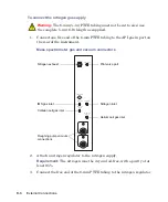
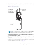
4. Set the nitrogen regulator to 700 kPa (7 bar, 102 psi).
5. Ensure that there are no gas leaks at any of the nitrogen gas supply
fittings.
Connecting to the collision cell gas supply
Required materials
•
Chemical-resistant, powder-free gloves
•
7/16-inch wrench
•
1/8-inch Swagelok
®
nut and ferrule
•
1/8-inch stainless steel tubing (supplied with the mass spectrometer)
•
Argon regulator (not supplied)
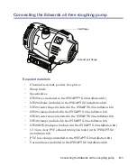
To connect the collision cell gas supply
1. Use the 1/8-inch Swagelok nut and ferrule to connect the 1/8-inch
stainless steel tubing to the collision cell gas inlet on the rear of the
mass spectrometer (see the figure on
2. Use the 7/16-inch wrench to tighten the 1/8-inch Swagelok nut.
3. Attach the argon regulator to the argon supply.
Requirement:
The argon must be dry and of high purity (99.997%).
4. Connect the free end of the tubing to the argon regulator.
5. Set the argon regulator to 50 kPa (0.5 bar, 7 psi).
6. Ensure that no gas leaks from any of the collision gas supply fittings.
Содержание SYNAPT G2
Страница 18: ...xviii Table of Contents...
Страница 46: ...2 8 Starting Up and Shutting Down the Mass Spectrometer...
Страница 66: ...3 20 Configuring the LockSpray Source...
Страница 228: ...B 24 External Connections 7 Click Next Result The software installs 8 Click Finish...
Страница 232: ...C 4 Materials of construction and compliant solvents...


