Waters ACQUITY Isocratic Solvent Manager Скачать руководство пользователя страница 103

Replacing the primary check valve

September 26, 2013, 715004208 Rev. A

103

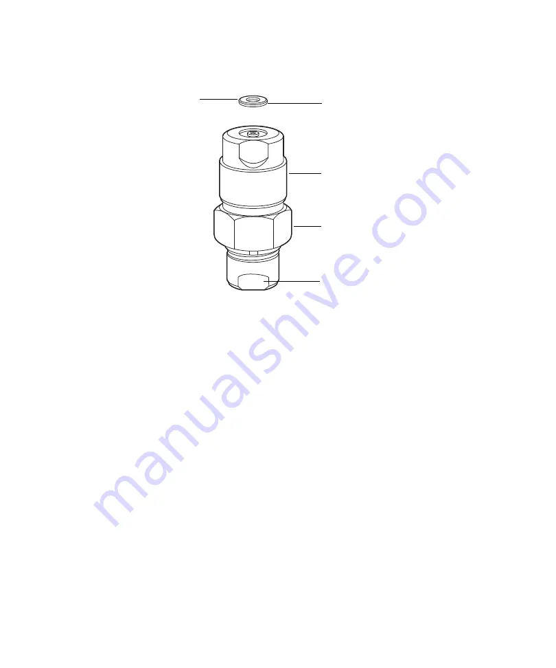
6. Ensure the new PEEK washer is inserted into the new check valve so 

that its chamfered edge faces away from the check valve.

7. Insert the check valve assembly into the head, and use the 1/2-inch 

wrench to tighten the check valve nut 1/8-turn beyond finger-tight.

8. Reattach the low-pressure filter holder to the check valve and 

finger-tighten it to the extent possible.

9. Power-on the ISM.

10. Prime the ISM (see 

page 67

).

PEEK washer

Check valve

Chamfered edge 
facing away from 
check valve

1/2-inch Hex nut

5/16-inch, open-end wrench flat

Содержание ACQUITY Isocratic Solvent Manager

Страница 1: ...ACQUITY Isocratic Solvent Manager Overview and Maintenance Guide 715004208 Revision A Copyright Waters Corporation 2013 All rights reserved...

Страница 2: ...ii September 26 2013 715004208 Rev A...

Страница 3: ...iable for incidental or consequential damages in connection with or arising from its use For the most recent revision of this document consult the Waters Web site waters com Trademarks ACQUITY ACQUITY...

Страница 4: ...rs instruments and devices can pose chemical biological or radiological hazards or any combination thereof You must know the potentially hazardous effects of all substances you work with Always follow...

Страница 5: ...nagement emissions notice This class A digital product apparatus complies with Canadian ICES 003 Cet appareil num rique de la classe A est conforme la norme NMB 003 Electrical power safety notice Do n...

Страница 6: ...Confirms that a manufactured product complies with all applicable European Community directives Australia C Tick EMC compliant Confirms that a manufactured product complies with all applicable United...

Страница 7: ...d for use in diagnostic applications Industrial scientific and medical classification Industrial scientific and medical classification Industrial Scientific and Medical Group 1 Class B This classifica...

Страница 8: ...6 2013 715004208 Rev A EC authorized representative Waters Corporation Micromass UK Ltd Floats Road Wythenshawe Manchester M23 9LZ United Kingdom Telephone 44 161 946 2400 Fax 44 161 946 2480 Contact...

Страница 9: ...otice v Safety advisories vi Operating this device vi Applicable symbols vi Audience and purpose vii Intended use of the isocratic solvent manager vii Industrial scientific and medical classification...

Страница 10: ...tional ACQUITY UPC2 Flow splitter kits 49 Installing the optional ACQUITY UPC2 Dual Detection Flow splitter kit 49 Installing the optional ACQUITY UPC2 Triple Detection Flow splitter kit 56 Installing...

Страница 11: ...low splitter kit 88 Replacing the inline 22 L filter 90 Replacing the low pressure filter cartridge 92 Replacing the vent valve cartridge 96 Replacing the cartridge in the optional solvent selection v...

Страница 12: ...3 Environmental specifications 154 Electrical specifications 154 Input output specifications 155 Performance specifications 155 ISM 155 ISM flow splitter kits 157 Wetted materials of construction 158...

Страница 13: ...e pump operates at a maximum pressure of 103 421 kPa 1034 bar 15 000 psi and flow rates as high as 1 mL min The pressure decreases linearly to 62 053 kPa 621 bar 9000 psi at flow rates up to 2 mL min...

Страница 14: ...ystem The following diagram shows the location of the ISM as a make up pump in a typical system that includes a QDa Quadrupole Dalton mass detector Note The ISM is typically located in the rightmost s...

Страница 15: ...reservoir Location of pressure transducer cable connector 2 Seal wash pump Drip tray Low pressure inlet filter Inline 22 L filter Accumulator check valve Seal wash waste tube Location of leak sensor c...

Страница 16: ...nsor detects approximately 1 5 mL of accumulated leaked liquid in its surrounding reservoir Note The leak sensor is part of the system kit and should be installed and configured in the software Low pr...

Страница 17: ...and Alliance systems Primary pump Draws solvent transferring it to the accumulator pump and system as part of the serial flow design Run LED Indicates the ISM status Sample manager purge solvent dega...

Страница 18: ...bels on the restrictor modules correspond to the magnitude of the split ratio as shown in the following tables Restrictor modules with higher numeric labels result in higher split ratios Label descrip...

Страница 19: ...on at the QDa detector percent mobile phase in make up flow mobile phase mixture entering QDa detector over a gradient elution for a selected restrictor module make up flow organic and make up flow co...

Страница 20: ...5 2 0 Methanol 10 organic 1 5 4 0 50 organic 1 4 3 6 Acetonitrile 10 organic 1 5 4 2 50 organic 1 6 4 4 Restrictor module 250 Make up flow Mobile phase concentration at QDa detector Organic Compositi...

Страница 21: ...organic 1 7 9 2 Methanol 10 organic 2 5 14 1 50 organic 2 3 13 0 Acetonitrile 10 organic 2 6 14 5 50 organic 2 6 15 1 Restrictor module 100 Make up flow Mobile phase concentration at QDa detector Org...

Страница 22: ...ce Flow splitter kit Note The splitter is configured with one of the three restrictor modules Solvent flows through the ISM with an installed ACQUITY UPLC or Alliance Flow splitter kit as follows 1 So...

Страница 23: ...two streams One stream is diluted with ISM solvent and diverted to the source of the QDa detector The other stream is diverted toward the optical detector undiluted Flow through the ISM with an instal...

Страница 24: ...solvent to the LC mobile phase and then splits the diluted mobile phase into two streams one flowing to the convergence manager and the other to the QDa detector Flow through the ISM with an installe...

Страница 25: ...vent flows to the UPC 2 Flow splitter 7 The UPC2 flow splitter adds the ISM solvent to the LC mobile phase and then splits the diluted mobile phase into three streams one flowing to the convergence ma...

Страница 26: ...vent to the accumulator the vent valve and the inline 22 L filter during transfer 5 The accumulator piston delivers solvent under pressure to the vent valve and the inline 22 L filter 6 From the inlin...

Страница 27: ...cking system modules 28 Installation recommendations for fittings 29 Installing the optional leak sensor 33 Resolving leak sensor errors 35 Installing the waste tubing and vent tubing for the degasser...

Страница 28: ...ackward until its rear alignment pin rests in the rear alignment slot on the QDa detector 2 Lower the front of the ISM so that its front alignment pin rests in the front alignment slot on the QDa dete...

Страница 29: ...e before tightening the compression fitting For easier accessibility use long compression screws to attach tubes to the injector and vent valve Perform the solvent manager leak test whenever you repla...

Страница 30: ...alled Long 1 4 28 fitting with flangeless ferrule and stainless steel lock ring installed on 1 8 inch outside diameter OD tubing Finger tight First use or reinstalled Long 1 4 28 fitting with flangele...

Страница 31: ...long flats and 2 piece stainless steel ferrule Finger tight plus 3 4 turn using wrench Reinstalled Stainless steel gold plated fitting with long flats and 2 piece stainless steel ferrule Finger tight...

Страница 32: ...r tight plus 3 4 turn using wrench Reinstalled Stainless steel gold plated fitting with short flats and 2 piece stainless steel ferrule Finger tight plus up to 1 6 turn using wrench Installation recom...

Страница 33: ...ve Good Laboratory Practices when you handle solvents change tubing or operate the ISM Consult the Material Safety Data Sheets regarding the solvents you use Warning The leak sensor can be contaminate...

Страница 34: ...to the right hand side of the leak sensor 4 Carefully unpack the new leak sensor 5 Align the leak sensor s T bar with the slot in the side of the leak sensor reservoir and slide the leak sensor into p...

Страница 35: ...lates in the leak sensor reservoir an alarm sounds indicating that the leak sensor detected a leak Warning To prevent injury always observe Good Laboratory Practices when you handle solvents change tu...

Страница 36: ...3 Open the ISM s door gently pulling its right hand edge toward you 4 Locate the source of the leak and make the repairs necessary to stop the leak Caution To avoid damaging electrical components or c...

Страница 37: ...ght hand side of the leak sensor 6 Remove the leak sensor from its reservoir grasping it by its serrations and pull upward on it Tip If you cannot easily manipulate the leak sensor after removing it f...

Страница 38: ...brasive lint free wipe and use it to absorb the liquid from the leak sensor reservoir and its surrounding area 9 With a cotton swab absorb any remaining liquid from the corners of the leak sensor rese...

Страница 39: ...e leak sensor into place 11 If you detached the connector from the receptacle on the front of the instrument reattach it 12 Power on the ISM 13 In the Instrument console select Isocratic Solvent Manag...

Страница 40: ...e waste tubing over the barbed drain fitting and route the tubing to a suitable waste container Caution To prevent contamination and possible contact with solvent wear clean chemical resistant powder...

Страница 41: ...arge end is at all times above the fluid level Warning To avoid spills and the subsequent release of solvent vapors empty the waste container at regular intervals Caution To avoid fluid backup you mus...

Страница 42: ...it and then diluted by the ISM flow before entering the detector The dilution compensates for that instrument s increased sensitivity as compared with the system s parallel UV UV VIS or PDA detector T...

Страница 43: ...esign but include different restrictor modules Required materials Gloves clean powder free chemical resistant ACQUITY UPLC or Alliance Flow splitter kit Required tool T10 TORX driver startup kit To in...

Страница 44: ...r remove the five screws that secure the blank face plate to the front face of the ISM chassis 3 Disconnect the vacuum tubing that is attached to the back of the degassing chamber Screws securing blan...

Страница 45: ...d label to the front of the face plate and then remove them from the face plate 5 Install the degasser and label on the flow splitter face plate assembly Secure the degasser and label to the face plat...

Страница 46: ...assembly in the front face of the ISM chassis Secure the face plate to the ISM with the screws removed in step 2 using the T10 TORX driver to tighten the screws Note The ACQUITY UPLC Flow splitter fac...

Страница 47: ...emove the black O rings prior to installing the tubing The O rings on the tubing are used to hold the fittings in place during shipping When making the tubing connection to inlet 2 connect the gold fi...

Страница 48: ...system the backpressure regulator is included with the ACQUITY detector Changing the split ratio Change the split ratio to adjust the amount of analytical flow split to the QDa detector General guidel...

Страница 49: ...e optional ACQUITY UPC 2 Flow splitter kits Install the optional ACQUITY UPC 2 Flow splitter kit to use an ACQUITY QDa Detector in an ACQUITY UPC2 system Note To ensure compliance with Japan s High Pr...

Страница 50: ...l Detection Flow splitter kit 1 Disconnect the finger tight fittings from the outlet and inlet of the degasser 2 Using the T10 TORX driver remove the five screws that secure the blank face plate to th...

Страница 51: ...he degassing chamber 4 Using the T10 TORX driver remove the screw that secures the degassing chamber and label to the front of the face plate and then remove them from the face plate 5 Install the dua...

Страница 52: ...the restrictor module to the extent possible 7 Install the degasser and label on the flow splitter face plate assembly Secure the degasser and label to the face plate assembly with the screw removed...

Страница 53: ...3 to the back of the degassing chamber that is now attached to the flow splitter face plate assembly 9 Install the Flow splitter assembly in the front face of the ISM chassis Secure the face plate to...

Страница 54: ...bing is supplied in the splitter kit 11 Connect the tubing as shown in the following diagram Tighten the inlet 2 from ISM filter and outlet 2 to convergence manager tee fittings 3 4 to 7 8 turn past f...

Страница 55: ...SM filter outlet tubing and Convergence Manager tee inlet tubing are supplied in the splitter kit 12 Reconnect the finger tight fittings to the outlet and inlet of the degasser Inlet 1 From optical de...

Страница 56: ...Detection Flow splitter kit To install the optional ACQUITY UPC 2 Triple Detection Flow splitter kit 1 Disconnect the finger tight fittings from the outlet and inlet of the degasser 2 Using the T10 T...

Страница 57: ...e degassing chamber 4 Using the T10 TORX driver remove the screw that secures the degassing chamber and label to the front of the face plate and then remove them from the face plate 5 Install the trip...

Страница 58: ...the restrictor module to the extent possible 7 Install the degasser and label on the flow splitter face plate assembly Secure the degasser and label to the face plate assembly with the screw removed...

Страница 59: ...3 to the back of the degassing chamber that is now attached to the flow splitter face plate assembly 9 Install the Flow splitter assembly in the front face of the ISM chassis Secure the face plate to...

Страница 60: ...hold the fittings in place during shipping The outlet 1 to inlet 3 tubing is supplied in the splitter kit 11 Connect the tubing as shown in the following diagram Tighten all fittings 3 4 to 7 8 turn...

Страница 61: ...alling the optional Post column Addition kit On an ACQUITY UPLC ACQUITY UPLC H Class ACQUITY UPLC I Class or Alliance system install the Post column Addition kit in the ISM to modify the composition o...

Страница 62: ...n unaffected by the kit s installation Required materials Gloves clean powder free chemical resistant Post column Addition kit Required tool T10 TORX driver startup kit To install the optional Post co...

Страница 63: ...Notes Remove the black O rings prior to installing the tubing The O rings on the tubing are used to hold the fittings in place during shipping When making the tubing connection to inlet 2 connect the...

Страница 64: ...f the power cord to a suitable wall outlet Priming the seal wash system Priming the seal wash system lubricates the ISM s plungers fills its tubing paths with solvent and flushes away solvent or any p...

Страница 65: ...h do not use a nonvolatile buffer as the seal wash solvent To avoid clogging system tubing ensure the seal wash solvent is 100 compatible with the mobile phase conditions To avoid spreading contaminat...

Страница 66: ...the syringe and then connect the syringe assembly to the seal wash system s outlet tubing 4 In the ACQUITY Console from the system tree select Isocratic Solvent Manager 5 Click Control Prime seal wash...

Страница 67: ...iming for 5 minutes uses about 20 mL of solvent Requirement You must ensure that the solvent tubing is primed with solvent in order for the degasser to function properly Priming a dry ISM via the cons...

Страница 68: ...path is primed Priming a dry ISM using a syringe Required materials Gloves clean powder free chemical resistant 30 mL syringe startup kit Short length of Pharmed tubing startup kit Tubing adapter sta...

Страница 69: ...ge 5 Connect the syringe assembly to a short length of Pharmed tubing and then connect the short length of Pharmed tubing to the solvent vent tubing you lifted from the drip tray in step 2 6 In the AC...

Страница 70: ...t tubing and reconnect the vent tubing to the drip tray Requirements Ensure that the solvent reservoir contains enough solvent for future methods All solvent tubing must contain solvent Monitoring LED...

Страница 71: ...low LED indications LED mode and color Description Unlit ISM is idle Steady green Solvent is flowing Flashing green Initializing and preparing for normal operation Flashing red Error state Refer to th...

Страница 72: ...e console Currently selected solvent Displays the currently selected solvent S1 S2 and so on If the optional solvent selection valve is not installed only S1 will display Flow rate Displays the flow r...

Страница 73: ...ates the plunger wash sequence which fills and then slowly empties the primary and accumulator chambers with the current solvent composition while performing a high speed volume seal wash This action...

Страница 74: ...2 Preparing for Operation 74 September 26 2013 715004208 Rev A...

Страница 75: ...cing the optional leak sensor 84 Replacing a restrictor module in the optional ACQUITY UPLC or Alliance Flow splitter kit 87 Replacing the restrictor module in the optional ACQUITY UPC 2 Flow splitter...

Страница 76: ...ions worldwide Visit www waters com When you contact Waters be prepared to provide this information Error message if any Nature of the symptom Serial number of the system module and its firmware versi...

Страница 77: ...sual representation of the system module for which you want to view information Obtain the serial number from the printed labels affixed to the rear panels of system modules or inside their front door...

Страница 78: ...ded See page 92 Replace the vent valve cartridge Every five years or as needed See page 96 Replace the cartridge in the optional solvent selection valve Ever five years or as needed See page 99 Replac...

Страница 79: ...tory Practice when handling solvents changing tubing or operating the instrument Know the physical and chemical properties of the solvents used see the Material Safety Data Sheets for the solvents in...

Страница 80: ...nt filter into the PTFE tubing pushing until it contacts the solvent tubing 4 Insert the filter end of the solvent tubing into the solvent bottle 5 Shake the filter to remove any air from it 6 Prime t...

Страница 81: ...the filter end of the solvent tubing from the solvent bottle ISM solvent filter Warning To prevent injury always observe Good Laboratory Practices when you handle solvents change tubing or operate the...

Страница 82: ...fitting and ferrule onto the solvent tubing 4 Insert the solvent tubing into the filter ensuring that it bottoms out in the filter 5 Screw the finger tight fitting and ferrule into the filter to secur...

Страница 83: ...ter removing it from the frame 2 Using a mild detergent and water clean the filter and then dry it 3 Align the cleaned air filter within the air filter frame Ensure the bottom of the air filter contac...

Страница 84: ...an powder free chemical resistant Leak sensor Warning To prevent injury always observe Good Laboratory Practices when you handle solvents change tubing or operate the ISM Consult the Material Safety D...

Страница 85: ...rument Caution To avoid damaging electrical components or circuitry of a system module do not disconnect an electrical assembly from the module while the module remains connected to the ac supply sour...

Страница 86: ...eak sensor s T bar with the slot in the side of the leak sensor reservoir and slide the leak sensor into place 7 Connect the leak sensor connector to the front of the instrument 8 Power on the ISM 9 I...

Страница 87: ...plitter kit Required materials Gloves clean powder free chemical resistant Restrictor module Required tool T10 TORX driver startup kit To replace a restrictor module 1 Disconnect the inlet 1 outlet 1...

Страница 88: ...dule to the extent possible 5 Connect the inlet 1 outlet 1 inlet 2 and outlet 2 tubing to the new restrictor module Tip To prevent contamination install plugs on any unused restrictor modules Replacin...

Страница 89: ...estrictor module 2 Using the T10 TORX driver loosen the two captive screws on the restrictor module and then remove the module 3 Insert the new restrictor module into the flow splitter assembly 4 Usin...

Страница 90: ...inch open end wrench 5 8 inch open end wrench 22 L mixer filter To replace the 22 L filter 1 Flush the ISM with non hazardous solvent 2 Stop the solvent flow 3 Holding the 22 L filter in place with t...

Страница 91: ...t the outlet compression fittings using the 1 4 inch wrench 5 Remove the old 22 L filter from the bracket 6 Unpack the new 22 L filter 7 Insert the new 22 L filter into the bracket 8 Reattach the comp...

Страница 92: ...location below the isocratic solvent manager Warning To avoid the harmful effects of personal contact with solvents including inhalation observe Good Laboratory Practice when you handle them See the...

Страница 93: ...ew the cap nut on the low pressure inlet filter assembly 5 Pull the cap nut off the tube to remove the low pressure filter cartridge Low pressure filter cartridge and cap nut Cap nut Cap nut Tube Low...

Страница 94: ...the tube ensuring that the thicker end of the metal locking ring is facing toward the cap nut Metal locking ring 8 Slide the new low pressure filter cartridge onto the tube Exploded view of low pressu...

Страница 95: ...10 Screw the cap nut onto the ferrule holder fitting ensuring that the tube is bottomed out in the in line filter cartridge Finger tighten it to the extent possible 11 Return the solvent bottles to t...

Страница 96: ...ation window click Interactive Display 3 In the ISM Interactive Display dialog box click Control 4 Ensure the vent valve is set to the Vent position Tip To change the setting to Vent click the underli...

Страница 97: ...osition on the vent valve cartridge 7 Remove the vent valve cartridge from the vent valve assembly by pulling straight forward Observe the orientation of the vent valve cartridge when doing so 8 Unpac...

Страница 98: ...s oriented The vent valve cartridge must slide fully into the vent valve assembly If it does not contact Waters Technical Service 11 Insert the 2 mm hex screw at the 10 o clock position on the vent va...

Страница 99: ...ratic Solvent Manager from the system tree 2 Ensure the solvent selection valve is set to solvent 6 3 Move the solvent bottles to a location below the ISM Warning To prevent injury always observe Good...

Страница 100: ...ight forward 7 Unpack the replacement cartridge 8 Ensure that the groove in the cartridge housing aligns with the groove on the drive clamp Tip If the grooves fail to align turn the drive clamp until...

Страница 101: ...to prime all six solvent tubes Replacing the primary check valve Required materials Primary check valve assembly Gloves clean powder free chemical resistant Required tool 1 2 inch open end wrench To...

Страница 102: ...wrench to loosen the check valve and then remove the check valve assembly from the head 5 Unpack the new check valve Caution When you remove the valve assembly ensure the PEEK washer which is normall...

Страница 103: ...sert the check valve assembly into the head and use the 1 2 inch wrench to tighten the check valve nut 1 8 turn beyond finger tight 8 Reattach the low pressure filter holder to the check valve and fin...

Страница 104: ...nd wrench To replace the accumulator check valve 1 Flush the ISM with non hazardous solvent 2 Power off the ISM Tip Move the solvent bottles to a location below the ISM Warning To prevent injury alway...

Страница 105: ...ing 4 Use the 1 2 inch open end wrench to loosen the check valve and then remove the check valve assembly from the head 5 Unpack the new check valve Caution When you remove the valve assembly ensure t...

Страница 106: ...nger tight 8 Use the 5 16 inch open end wrench to hold the check valve in place and then reattach the compression fitting to the check valve Tip Use the 1 4 inch wrench to tighten the compression fitt...

Страница 107: ...and plunger seal spacer Fluoropolymer O ring Seal wash seal Required tools 1 4 inch open end wrench 5 16 inch open end wrench Plunger removal tool recommended Seal extraction tool Sharp tool T27 TORX...

Страница 108: ...vent bottles to a location below the solvent manager 8 Unscrew the low pressure filter holder from the primary check valve inlet Caution To avoid damaging electrical components or circuitry of a syste...

Страница 109: ...wash tubing secured to the seal wash housing by barbed fittings by using a tool or by pulling on the tubing as close to the pump head as possible 10 Use the 1 4 inch open end wrench to disconnect the...

Страница 110: ...the pressure transducer cable from the bulkhead by squeezing on the tabs and pulling gently 12 Using the T27 TORX driver loosen the two head bolts 1 2 turn The bolts are accessible from the front of...

Страница 111: ...2 support plate bolts and then gently pull the head and support plate off the actuator housing making sure not to tilt the head during the extraction Pulling head and support plate off actuator housi...

Страница 112: ...s of the release collar and then remove the old plunger 15 Remove the plunger removal tool from the release collar Warning To avoid hand lacerations use care when removing the old plunger Bending the...

Страница 113: ...clean surface 2 Using the T27 TORX driver completely loosen the two head bolts to release the support plate from the pump head Requirement If you remove the transducer and head bolts be sure to reuse...

Страница 114: ...eal wash seal and discard it Head seals 5 Using the smooth end of the seal extraction tool remove the plunger seal spacer from the head Seal wash housing Seal wash seal Head Fluoropolymer O ring Plung...

Страница 115: ...seal from the head 7 Taking care not to scratch any surfaces use a sharp tool to remove the fluoropolymer O ring Caution To avoid scratching any metal surfaces use care when screwing the threaded end...

Страница 116: ...w fluoropolymer O ring with methanol and press the O ring into its seat with your thumbs 10 Spray the new plunger seal with compressed air to remove any particulates 11 Lubricate the new plunger seal...

Страница 117: ...he plunger seal so that the cross side faces upward 13 Orient the seal wash housing so that the holes on its side align with the holes on the side of the head and then guide it into place 14 Spray the...

Страница 118: ...ll the new seal wash seal in the seal wash housing 16 Place the support plate on top of the pump head ensuring the round side of the plate is oriented toward the bottom side of the head Seal wash seal...

Страница 119: ...tighten the two head bolts until screw bottoms out then unscrew 1 4 turn To reattach the primary head 1 Flip the assembly over and then lubricate the seals with methanol 2 Carefully insert the sapphir...

Страница 120: ...place the plunger seal 3 Carefully slide the head assembly and sapphire plunger into the actuator housing making sure not to tilt the head Caution To avoid damaging the plunger ensure that the head as...

Страница 121: ...y head 10 Click Move Forward and then wait for the piston to engage the plunger sphere 11 Use the torque driver to tighten each pump head bolt to 40 inch pounds of torque 12 After tightening each pump...

Страница 122: ...heir original location 16 Prime the ISM see page 67 17 Perform the ISM leak test see the Instrument console online Help If the leak test results are not satisfactory pressurize the head plunger seals...

Страница 123: ...d plunger seal spacer Fluoropolymer O ring Seal wash seal Required tools 1 4 inch open end wrench 5 16 inch open end wrench Plunger removal tool recommended Seal extraction tool Sharp tool T27 TORX dr...

Страница 124: ...ck Move Backward and then wait for the plunger to stop 6 Power off the ISM 7 Move the solvent bottles to a location below the ISM Caution To avoid damaging electrical parts never disconnect an electri...

Страница 125: ...the seal wash tubing secured to the seal wash housing by barbed fittings by using a tool or by pulling on the tubing as close to the pump head as possible 9 Using the 1 4 inch open end wrench disconn...

Страница 126: ...ridge in place disconnect the tubing connection from the check valve with the 1 4 inch open end wrench 11 Disconnect the pressure transducer cable from the bulkhead by squeezing on the tabs and pullin...

Страница 127: ...accessible from the front of the pressure transducer 13 Using the T27 TORX driver loosen and remove the 2 support plate bolts and then gently pull the head and support plate off the actuator housing m...

Страница 128: ...3 Maintenance Procedures 128 September 26 2013 715004208 Rev A Pulling head and support plate off actuator housing Head and support plate Plunger...

Страница 129: ...ssure to both sides of the release collar and then remove the old plunger 15 Remove the plunger removal tool from the release collar Warning To avoid hand lacerations use care when removing the old pl...

Страница 130: ...ce 2 Using the T27 TORX driver completely loosen the two head bolts to release the support plate from the pump head Requirement If you remove the transducer and head bolts be sure to reuse the head bo...

Страница 131: ...emove the old seal wash seal and discard it Head seals 5 Using the smooth end of the seal extraction tool remove the plunger seal spacer from the head Seal wash housing Seal wash seal Head Fluoropolym...

Страница 132: ...tool to remove the fluoropolymer O ring 8 Inspect the pump head surface ensuring it is free from scratches and particulates Caution To avoid scratching any metal surfaces use care when screwing the th...

Страница 133: ...methanol and press the O ring into its seat with your thumbs 10 Spray the new plunger seal with compressed air to remove any particulates 11 Lubricate the new plunger seal with methanol and use the s...

Страница 134: ...lunger seal spacer over the plunger seal so that the cross side faces upward 13 Orient the seal wash housing so that the holes on its side align with the holes on the side of the head and then guide i...

Страница 135: ...and replacing its seals September 26 2013 715004208 Rev A 135 14 Spray the seal wash seal with compressed air to remove any particulates 15 Install the new seal wash seal in the seal wash housing Sea...

Страница 136: ...pump head ensuring the round side of the plate is oriented toward the bottom side of the head 17 Holding the assembly together using the T27 TORX driver fully tighten the two head bolts until the scre...

Страница 137: ...Rev A 137 To reattach the accumulator head 1 Flip the assembly over and then lubricate the seals with methanol 2 Carefully insert the sapphire plunger shaft into the pump head until the plunger shaft...

Страница 138: ...er you replace the plunger seal 3 Carefully slide the head assembly and sapphire plunger into the actuator housing making sure not to tilt the head Caution To avoid damaging the plunger ensure that th...

Страница 139: ...ard and then wait for the piston to engage the plunger sphere 11 Use the torque driver to tighten each pump head bolt to 40 inch pounds of torque 12 After tightening each pump head bolt to 40 inch pou...

Страница 140: ...until results are satisfactory Cleaning the instrument s exterior Clean surfaces of the solvent manager using only a clean soft lint free paper or clean cloth dampened with water Warning To avoid ele...

Страница 141: ...ce The symbols also appear in product manuals where they accompany statements describing the hazards and advising how to avoid them This appendix presents the safety symbols and statements that apply...

Страница 142: ...or a component of an instrument or device When one of these symbols appear in a manual s narrative sections or procedures an accompanying statement identifies the applicable risk and explains how to...

Страница 143: ...osion Warning Risk of eye injury Warning To prevent injury always observe Good Laboratory Practices when you handle solvents change tubing or operate the ISM Consult the Material Safety Data Sheets re...

Страница 144: ...avoid personal contamination with biohazards toxic materials or corrosive materials you must understand the hazards associated with their handling Guidelines prescribing the proper use and handling o...

Страница 145: ...de la conformit la r glementation peut annuler le droit de l utilisateur exploiter l quipement Achtung Jedwede nderungen oder Modifikationen an dem Ger t ohne die ausdr ckliche Genehmigung der f r die...

Страница 146: ...me se trouvant proximit de l instrument Evitez d utiliser des tubes s v rement d form s ou endommag s Evitez d utiliser des tubes non m talliques avec du t trahydrofurane THF ou de l acide sulfurique...

Страница 147: ...il dimetilsolfossido provocano rigonfiamenti nei tubi non metallici riducendo notevolmente la pressione di rottura dei tubi stessi Advertencia se recomienda precauci n cuando se trabaje con tubos de p...

Страница 148: ...A Safety Advisories 148 September 26 2013 715004208 Rev A Nonmetallic Tetrahydrofuran THF Methylene chloride Dimethyl sulfoxide THF...

Страница 149: ...e par le mat riel risque d tre d fectueuses Vorsicht Der Benutzer wird darauf aufmerksam gemacht dass bei unsachgem er Verwenddung des Ger tes die eingebauten Sicherheitseinrichtungen unter Umst nden...

Страница 150: ...al symbols The following electrical symbols and their associated statements can appear in instrument manuals and on an instrument s front or rear panels Electrical power on Electrical power off Standb...

Страница 151: ...715004208 Rev A 151 Handling symbols The following handling symbols and their associated statements can appear on labels affixed to the packaging in which instruments devices and component parts are s...

Страница 152: ...A Safety Advisories 152 September 26 2013 715004208 Rev A...

Страница 153: ...cations Physical specifications The following table lists the physical specifications for the ISM Contents Topic Page Physical specifications 153 Environmental specifications 154 Electrical specificat...

Страница 154: ...Class I identifies a single level of insulation between live parts wires and exposed conductive parts metal panels in which the exposed conductive parts are connected to a grounding system In turn thi...

Страница 155: ...is a placeholder that identifies protection against dust if applicable Input and output specifications Attribute Specification Gradient start Maximum input voltage 30 VDC Logic High 3 0 VDC Logic Low...

Страница 156: ...er Provides pulsed flow of 50 20 L per pulse Maximum operating pressure ISM only Note For flow splitter pressure information see page 157 0 to 1 mL min 103 425 kPa 1034 bar 15 000 psi 1 to 2 mL min 10...

Страница 157: ...18 1 7 m 2 1 50 mm Column temperature 35 C 1 0 C Detector 254 nm UV Dynamic leak test 50 to150 nL min at 20 684 to 96 527 kPa 207 to 965 bar 3000 to 14 000 psi accumulator pressure Static leak test 50...

Страница 158: ...lit ratio Note This specification applies to replacing an individual restrictor module only UPC2 Flow splitter kit performance specifications Item Specification Flow rate Up to 4 0 mL min Pressure 41...

Страница 159: ...f construction for the UPC 2 Flow splitter kit Post column Addition kit The following table lists the wetted materials of construction for the Post column Addition kit Wetted materials of construction...

Страница 160: ...B Specifications 160 September 26 2013 715004208 Rev A...

Отзывы: