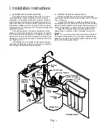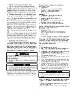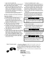
J. MAKE THE TUBING CONNECTIONS
With all of the components in place, the tubing connections
can be made. When routing the tubing between the compo-
nents, several guidelines should be observed.
•
Tubing runs should generally follow the contour of the
cabinet rather than interfere with the cabinet storage area.
•
Strive for a neat and orderly tubing “flow” by using
fasteners (e.g. insulated staples) to secure the tubing.
•
Arrange the tubing so that there are no sharp bends.
Leave some “play” in the tubing for ease of servicing, then
cut the tubing to the desired length.
•
Try to keep the tubing from the filtration assembly to the
tank and faucet as short as practical for good flow.
For Basement Installation See Installation Instructions O.
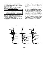
Undercounter Installation:
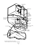
The appliance will have the 3/8” yellow and the 3/8” blue
tubing already connected to the filtration assembly.
1) The 1/4” orange tubing should already have been
connected to the cold water supply shut off valve.
Route the other end through the large opening in the “
bottom of the metal bracket and loop it back to the “Feed”
connection on the filtration assembly.
2) Attach the 1/4” x 3/8” union to 1/4” blue tubing on faucet.
3) Connect the 3/8” blue tubing from the filtration
assembly to the other end of 3/8” x 1/4” union.
4) Route the 3/8” black tubing from the faucet air gap to the
drain saddle so that it slopes continuously downward
without any loops or low spots. Cut the tubing to the
proper length and connect it to the drain saddle elbow.
5) Connect the 3/8” yellow tubing from the filtration
assembly to the tank.
6) Remove the plug from the elbow fitting on the RO module
cartridge. Insert the special SFC tube into this elbow fitting.
(Note: The elbow fitting is labeled “drain” on the RO
module.) Route the special red SFC tubing toward the
faucet.
Do not cut this special SFC tubing. Its length is
important to maintain proper efficiency and performance.
7) Cut the 1/4” green tubing from the faucet air gap to the
proper length and connect it to the1/4” connector fitting on
the end of the SFC tubing.
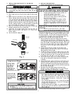
K. INSTALL THE ICEMAKER HOOKUP (optional)
The RO drinking water appliance can be connected to any
standard refrigerator icemaker or icemaker/water dispenser. It
should never be connected to a commercial type bar icemaker.
Hooking up an icemaker involves connecting a tee with a
shut off valve into the 3/8” blue faucet tubing and routing the
tubing over to the refrigerator. Hooking up to existing copper
unit is generally not recommended unless it is less than six
months old. If copper tubing must be used, then the installa-
tion of a small in-line carbon filter at the refrigerator connection
is recommended.
Before turning off the existing tap water supply to the refrig-
erator icemaker, always shut off the icemaker first (usually by
lifting the lever arm above the bin to the uppermost position).
The icemaker should only be turned on again
after the RO
system has been drained several times and the storage tank
has a
full supply of water.
IMPORTANT NOTES
• Before any service is performed on the RO appliance, al-
ways turn off the icemaker valve and the icemaker unit.
Only turn them on when the system is operating and the
tank is full.
L. START UP THE APPLIANCE
1) Double check to see that all of the connections are secure.
2) Open the cold water supply shut off valve and check the
appliance for leaks. If any leaks are detected, close the
valve and correct the problem before proceeding.
IMPORTANT NOTE
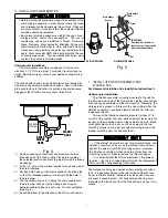
If a leak occurs at a “Push In” plastic fitting, then refer to Fig. 6.
3) Open the storage tank valve and lift the faucet handle until
a steady stream of water flows. Close the faucet, wait at
least 5 minutes and carefully check for leaks. Correct
them as necessary.
IMPORTANT NOTE
When the appliance is first turned on, water may intermittently
“spurt” from the air gap opening at the side of the faucet. This
is perfectly normal, and is caused by air trapped in the sys-
tem. This will usually disappear within a short time.
8
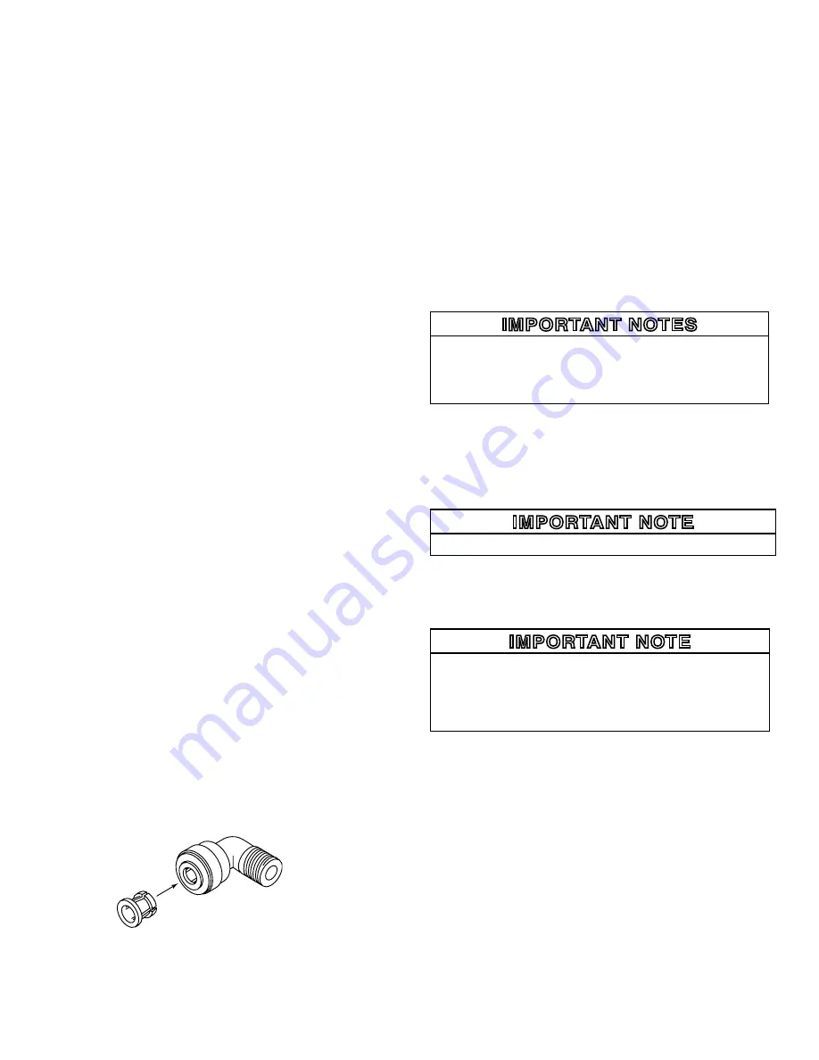
This product is outfitted with user friendly ‘Push In’ connectors. Proper use of the
connectors is shown in Figure 3.
It is most important that the tubing selected for use with these connectors be of
high quality, exact size and roundness, and with no surface nicks or scratches. If it is
necessary to cut the tubing, use a plastic tubing cutter or sharp razor knife. Make a
clean square cut.
Should a leak occur at a ‘Push-In’ connector, the cause is usually defective tubing.
To Fix: • Relieve pressure
• Release tubing
• Cut off at least 1/4” from end.
• Reattach tubing
• Confirm connection is leak free.
‘Push-In’ Tubing Connector
Fig. 6


