


Wärtsilä JOVYTEC PMS 6000 BAX 2935_en
- 30 -
9.2
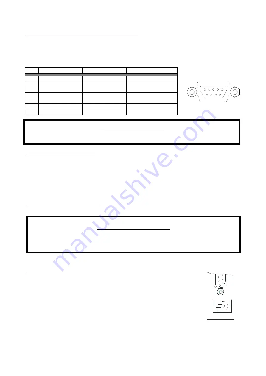
Assignment of the RS232 interface
The RS 232 interface uses a 9-pin SUB-D connector (jack). Assignment of the SUB-D connector is as
described in the table below.
Pin assignment for the RS 232 interface RS 232 interface
(Rear side of UPS)
PIN SIGNAL
DIRECTION
FUNCTION
2 TxD
Output
TxD output
3 RxD
Input
RxD/inverter out
Input
5 GND
GND
6 CTS
Output
AC fault on output
8 DCD
Output
Discharge battery
9 RI
Output
+8/-24 VDC
Graphic 16: RS232 interface
9.3
USB port (optional)
Connection of the UPS to a computer is also possible via the USB interface at the rear of the UPS unit. If the
USB interface is to be used then simultaneous use of the RS 232 interface is not possible. Communication
between the UPS and the computer takes place via a conventional USB connection cable (PC: plug -A /
UPS unit: plug -B) and can only be used with the software “
UPSMON
“ delivered as standard and the
optionally obtainable JUMP software.
10.
Special equipment
10.1
Electronic STOP function
The UPS is fitted with an integrated electronic STOP function. This function is
deactivated as standard via a bridge at the rear of the UPS unit. If the electronic
STOP functionality is to be used then the bridge should be removed on the plug
and an external switch (opener) clamped to the rear plug. Actuation of the
external electronic STOP switch causes the output of the UPS unit to be
switched to voltage-free and the UPS unit shuts down. In order to provide the
consumers with a voltage again the electronic STOP switch must be reset and
the UPS restarted. There is still a
voltage
inside and at the terminals even after
the electronic STOP function was activated.
Graphic 17: Electronic STOP
1
2
3
4
5
6
7
8
9
P L E A S E N O T E!
The following conversion work or extension to the unit may only be performed by
trained personnel and with the UPS unit in a deenergised condition.
Observe the relevant safety regulations!!
P L E A S E N O T E!
Maximum value 24VDC/50mA!
Содержание JOVYTEC POWERMASTER PMS 6000
Страница 2: ...Operating Manual W rtsil JOVYTEC PMS 6000 BAX 2935 E...
Страница 17: ...W rtsil JOVYTEC PMS 6000 BAX 2935_en 16 5 6 2 Powermaster S 6000 mounted in 19 Cabinet...
Страница 18: ...W rtsil JOVYTEC PMS 6000 BAX 2935_en 17 5 6 3 Powermaster S 6000 as Table Device...
Страница 34: ...W rtsil JOVYTEC PMS 6000 BAX 2935_en 33...