pressure of the circulating pumps may rise to 1.05 MPa (10.5 bar), and the safety valve of the
pump shall thus be adjusted e.g. to 1.2 MPa (12 bar).
●
A design pressure of not less than 1.2 MPa (12 bar) has to be selected.
●
The nearest pipe class to be selected is PN16.
●
Piping test pressure is normally 1.5 x the design pressure = 1.8 MPa (18 bar).
Example 2:
The pressure on the suction side of the cooling water pump is 0.1 MPa (1 bar). The delivery
head of the pump is 0.3 MPa (3 bar), leading to a discharge pressure of 0.4 MPa (4 bar). The
highest point of the pump curve (at or near zero flow) is 0.1 MPa (1 bar) higher than the nominal
point, and consequently the discharge pressure may rise to 0.5 MPa (5 bar) (with closed or
throttled valves).
●
The minimum design pressure is 0.5 MPa (5 bar) shall be selected.
●
The nearest pressure class to be selected is PN6.
●
Piping test pressure is normally 1.5 x the design pressure = 0.75 MPa (7.5 bar).
Standard pressure classes are PN4, PN6, PN10, PN16, PN25, PN40, etc.
5.4
Pipe class
Classification societies categorize piping systems in different classes (DNV) or groups (ABS)
depending on pressure, temperature and media. The pipe class can determine:
●
Type of connections to be used
●
Heat treatment
●
Welding procedure
●
Test method
Systems with high design pressures and temperatures and hazardous media belong to class
I (or group I), others to II or III as applicable. Quality requirements are highest in class I.
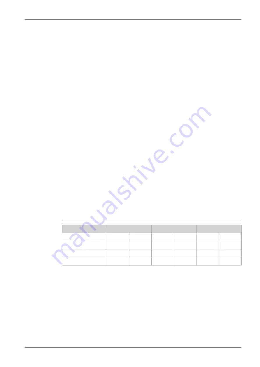
Examples of classes of piping systems as per DNV rules are presented in the table below.
Table 5-2
Classes of piping systems as per DNV rules
Class III
Class II
Class I
Media
°C
MPa (bar)
°C
MPa (bar)
°C
MPa (bar)
and < 170
< 0.7 (7)
and < 300
< 1.6 (16)
or > 300
> 1.6 (16)
Steam
and < 60
< 0.7 (7)
and < 150
< 1.6 (16)
or > 150
> 1.6 (16)
Flammable fluid
and < 200
< 1.6 (16)
and < 300
< 4 (40)
or > 300
> 4 (40)
Other media
5.5
Insulation
The following pipes shall be insulated:
●
All trace heated pipes
●
Exhaust gas pipes
●
Exposed parts of pipes with temperature > 60°C
Insulation is also recommended for:
●
Pipes between engine or system oil tank and lubricating oil separator
DAAB605814
5-3
5. Piping Design, Treatment and Installation
Wärtsilä 46F Product Guide
Содержание 46F Series
Страница 1: ...Wärtsilä 46F PRODUCT GUIDE ...
Страница 4: ...This page intentionally left blank ...
Страница 8: ...This page intentionally left blank ...
Страница 18: ...This page intentionally left blank ...
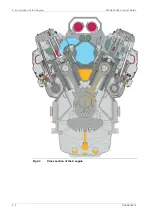
Страница 46: ...Fig 4 3 Cross section of the V engine 4 6 DAAB605814 Wärtsilä 46F Product Guide 4 Description of the Engine ...
Страница 86: ...This page intentionally left blank ...
Страница 104: ...This page intentionally left blank ...
Страница 154: ...This page intentionally left blank ...
Страница 162: ...This page intentionally left blank ...
Страница 170: ...This page intentionally left blank ...
Страница 176: ...This page intentionally left blank ...
Страница 194: ...This page intentionally left blank ...
Страница 200: ...This page intentionally left blank ...
Страница 202: ...This page intentionally left blank ...
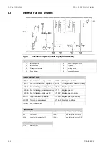
Страница 207: ...Fig 21 7 List of symbols DAAF406507 7 DAAB605814 21 5 21 ANNEX Wärtsilä 46F Product Guide ...

