10.
Combustion Air System
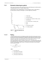
10.1
Engine room ventilation
To maintain acceptable operating conditions for the engines and to ensure trouble free operation
of all equipment, attention shall be paid to the engine room ventilation and the supply of
combustion air.
The air intakes to the engine room must be located and designed so that water spray, rain
water, dust and exhaust gases cannot enter the ventilation ducts and the engine room.
The dimensioning of blowers and extractors should ensure that an overpressure of about 50
Pa is maintained in the engine room in all running conditions.
For the minimum requirements concerning the engine room ventilation and more details, see
applicable standards, such as ISO 8861.
The amount of air required for ventilation is calculated from the total heat emission
Φ
to
evacuate. To determine
Φ
, all heat sources shall be considered, e.g.:
●
Main and auxiliary diesel engines
●
Exhaust gas piping
●
Generators
●
Electric appliances and lighting
●
Boilers
●
Steam and condensate piping
●
Tanks
It is recommended to consider an outside air temperature of no less than 35°C and a
temperature rise of 11°C for the ventilation air.
The amount of air required for ventilation is then calculated using the formula:
where:
q
v
= air flow [m³/s]
Φ
= total heat emission to be evacuated [kW]
ρ
= air density 1.13 kg/m³
c = specific heat capacity of the ventilation air 1.01 kJ/kgK
Δ
T = temperature rise in the engine room [°C]
The heat emitted by the engine is listed in chapter Technical data.
The engine room ventilation air has to be provided by separate ventilation fans. These fans
should preferably have two-speed electric motors (or variable speed). The ventilation can then
be reduced according to outside air temperature and heat generation in the engine room, for
example during overhaul of the main engine when it is not preheated (and therefore not heating
the room).
The ventilation air is to be equally distributed in the engine room considering air flows from
points of delivery towards the exits. This is usually done so that the funnel serves as exit for
most of the air. To avoid stagnant air, extractors can be used.
DAAB605814
10-1
10. Combustion Air System
Wärtsilä 46F Product Guide
Содержание 46F Series
Страница 1: ...Wärtsilä 46F PRODUCT GUIDE ...
Страница 4: ...This page intentionally left blank ...
Страница 8: ...This page intentionally left blank ...
Страница 18: ...This page intentionally left blank ...
Страница 46: ...Fig 4 3 Cross section of the V engine 4 6 DAAB605814 Wärtsilä 46F Product Guide 4 Description of the Engine ...
Страница 86: ...This page intentionally left blank ...
Страница 104: ...This page intentionally left blank ...
Страница 154: ...This page intentionally left blank ...
Страница 162: ...This page intentionally left blank ...
Страница 170: ...This page intentionally left blank ...
Страница 176: ...This page intentionally left blank ...
Страница 194: ...This page intentionally left blank ...
Страница 200: ...This page intentionally left blank ...
Страница 202: ...This page intentionally left blank ...
Страница 207: ...Fig 21 7 List of symbols DAAF406507 7 DAAB605814 21 5 21 ANNEX Wärtsilä 46F Product Guide ...

