background image

-4- 


DG12S Components 


Item


Description


Quantity


1


Control gate


1


2


Control panel


1


3


Battery boards


1


4


Front cover


1


5


Left door


1


6


Upper plate


1


7


Rubbe rcover


1


8


Alternator clapboard


1


9


Alternator


1


10


Muffler heat 
insulation cover


1


11


Muffler assy


1


12


Engine


1


Item


Description


Quantity


13


Muffler assy


1


14


Shock absorber


6


15


Battery


1


16


Inner cover


1


17


Air cover


1


18


Back cover


1


19


Bottom seat


1


20


Fuel tank


1


21


Wheel


2


22


Lock wheel


2


23


Door lock cover


2


24


Right door


1


Содержание LDG12S

Страница 1: ...WARRIOR GENERATORS USER MANUAL FOR MODELS LDG12S LDG12S3...

Страница 2: ...Before Start DG12 Check Before Operation 5 DG12S Check Before Operation 6 5 Operation 7 6 Stopping Generator 7 7 Maintenance DG12 Check and Maintenance DG12S Check and Maintenance 9 10 8 Appendix and...

Страница 3: ...tion while the generator set is shut down and isolated Diesel Fuel is combustible and can ignite Do not overfill the fuel tank fill to recommended level on gauge Make sure the fuel cap is tightly secu...

Страница 4: ...Brushless AC single phase Brush AC three phase Frequency Hz 50 60 Voltage V 110 115 120 220 230 240 110 220 115 230 120 240 220 380 230 400 110 115 120 220 230 240 110 220 115 230 120 240 220 380 230...

Страница 5: ...on Quantity 1 Top cover 1 2 Frame 1 3 Engine side cover 1 4 Front cover 1 5 Muffler assy 1 6 Air cleaner assy 1 7 Engine 1 8 Shock absorber 6 9 Lock wheel 2 10 Alternator 1 11 Wheel 2 12 Control panel...

Страница 6: ...1 7 Rubbe rcover 1 8 Alternator clapboard 1 9 Alternator 1 10 Muffler heat insulation cover 1 11 Muffler assy 1 12 Engine 1 Item Description Quantity 13 Muffler assy 1 14 Shock absorber 6 15 Battery 1...

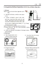
Страница 7: ...s lower limit when take out the ways of adding oil as below 7 1 Finally install and plug oil gauge Notice DO NOT run generator with low oil level or below Minimum this will cause generator engine part...

Страница 8: ...r engine parts to damage 2 Fuel level Caution Please refuel in a well ventilated area make sure there is NO cigarettes naked flames or sparks when refuel Open left door check the fuel level indicator...

Страница 9: ...esn t start please wait for about 30 seconds OFF ON before attempting to start again 3 AC application In accordance with the actual situation to connect the load through the load terminals or wiring s...

Страница 10: ...e The first month or 20 hours Every three months or 100 hours Every three months or 100 hours Oil Check Renew First time Second time Air cleaner element Check Clean The valve gap Check adjust The liqu...

Страница 11: ...rain plug back Open the lock over the front cover 4 1 screw the cylinder head oil cap 2 as the photo pull the oil until reach the oil gauge max limited 4 1 in the end screw back the cylinder head stud...

Страница 12: ...lace drain plug back Move the plastic rounded lid on the top of genset unscrew the cylinder head oil cap fill the oil until reach the oil gauge max limited 4 1 in the end screw back the cylinder head...

Страница 13: ...storage 2 Storage instructions Do not touch the muffler Around the exhaust port of the muffler is very hot while generator is running and the heat will remain for some time after generator stops To pr...

Страница 14: ...n or rings in wrong place Change and adjust piston ring Valve clearance is not correct Adjust the clearance as per operational manual Bolts of cylinder head are not tight Re tight the bolt Check fuel...

Страница 15: ...13 10 Electrical Wiring Diagram Single Phase Generator 11 Electrical Wiring Diagram Three Phase Generator...

Отзывы: