


50
Before commissioning installation water must be fed through the filling and emptying cock
until water flows out of the overflow on the open expansion vessel. In the case of a closed
system, an over pressure of 1 to 1.5 bar must be created. In any case attention has to be
paid to slowly filling the system and the exhausting air through the integrated ventilation
valve before the above mentioned static pressure is reached or before the expansion ves-
sel overflows.
The closed system is recommended if possible for corrosion safety reasons. Corrosion
damage to domestic water boilers and stove boilers in open systems and to radiators be-
cause unhindered ingress of oxygen to the hot water cannot be excluded in the long term
domestic water may be taken from the heating circuit.
No domestic water may be taken from the heating circuit. Taking domestic water is only
permitted indirectly through intermediate heat exchangers (double shelled boilers or
through flow boilers).
The safety flow and return as well as the pipes to and from the domestic water boiler may
not be less than 1" diameter. Closed systems require a safety valve with an opening pres-
sure of 2.5 bar built into the flow line.
The manufacturer does not give a guarantee on corrosion damage to stove boilers, if non-
ferrous metals are used in the hot water circulation in open systems, in cases where no
suitable corrosion protection medium in accordance with the manufacturer's recommenda-
tions.
4.3 Integrating in an existing unit
The stove with integrated heat exchanger for the heat sink is suitable for incorporating in
existing units which are constructed as closed systems.
The safety valve on the central heating boiler in the cellar cannot cover the heating stove
as well. A separate safety valve should in any case be provided near the heating stove.
It is absolutely necessary to consume, respectively to store up the energy of the added
cooker. A buffer reservoir of 50 litres per kW water output is normally sufficient for buffer-
ing.
Содержание K158
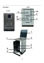
Страница 4: ...4 Geräteaufbau 1 9 2 6 4 8 7 13 5 3 10 12 11 K158F K158 ...
Страница 25: ...25 Bild 8 Bild 7 Bild 9 Bild 10 a b Bild 11 ...
Страница 26: ...26 Bild 12 Bild 13 Bild 14 Bild 15 Bild 16 Bild 17 ...
Страница 27: ...27 Bild 19 Bild 18 Bild 20 ...
Страница 29: ...29 Bild 29 Bild 30 Bild 33 Bild 31 Bild 32 Bild 35 Bild 36 Bild 34 ...
Страница 32: ...32 ...
Страница 33: ...33 ...
Страница 34: ...34 ...
Страница 37: ...37 Assembly K158 1 9 2 6 4 8 7 13 5 3 10 12 11 K158F ...
Страница 56: ...56 Pic 8 Pic 7 Pic 9 Pic 10 a b Pic 11 ...
Страница 57: ...____________________________________________________________ 57 Pic 12 Pic 13 Pic 14 Pic 15 Pic 16 Pic 17 ...
Страница 58: ...____________________________________________________________ 58 Pic 19 Pic 18 Pic 20 ...
Страница 59: ...59 Pic 23 Pic 24 Pic 25 Pic 26 Pic 27 Pic 28 ...
Страница 65: ...65 Structure de l appareil K158 K158F 1 9 2 6 4 8 7 13 5 3 10 12 11 ...
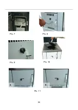
Страница 81: ...81 fig 8 fig 7 fig 9 fig 10 a b fig 11 ...
Страница 82: ...82 fig 12 fig 13 fig 14 fig 15 fig 16 fig 17 ...
Страница 83: ...83 fig 19 fig 18 fig 20 ...
Страница 84: ...84 fig 23 fig 24 fig 25 fig 26 fig 27 fig 28 ...
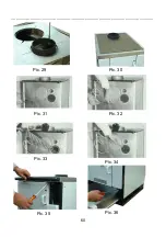
Страница 85: ...85 fig 30 fig 35 fig 36 fig 34 fig 29 fig 33 fig 31 fig 32 ...
Страница 90: ...90 Struttura dell apparecchio K158 K158F 1 9 2 6 4 8 7 13 5 3 10 12 11 ...
Страница 111: ...111 fig 8 fig 7 fig 9 fig 10 a b fig 11 ...
Страница 112: ...112 fig 12 fig 13 fig 14 fig 15 fig 16 fig 17 ...
Страница 113: ...113 fig 19 fig 18 fig 20 ...
Страница 114: ...114 fig 23 fig 24 fig 25 fig 26 fig 27 fig 28 ...
Страница 115: ...115 fig 33 fig 35 fig 36 fig 34 fig 29 fig 30 fig 31 fig 32 ...
Страница 118: ......
Страница 119: ...119 ...


