


44
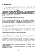
2. ARRANGEMENT
For installation and for connection of flue, the requirements of the Fire Regulations (FeuVO
in Germany) apply, as well as local building regulations such as the following technical
standards DIN 4705, EN 13384, DIN 18160, EN 1856-2, EN 12828, EN 12831, EN 12897
and EN 15287. In order for the stove to function correctly the chimney to which you want to
connect the stove must be in good condition.
NOTE
The room must reach the so-called room capacity ratio of 4 m
3
per kW nominal heat
capacity. If this is not possible, then it has to be connected to other rooms on an air
flow sense, i.e. with rooms with outside doors or windows and air vents in the con-
necting doors or walls to the installation room.
2.1 Fire safety
All flue pipes must be capable of withstanding up to +400 °C.
If the stove is to be installed on a floor of combustible material such as wood or plastic etc.,
then a floor plate must be installed which is larger than the footprint of the stove from the
fire door to each side by at least
30 cm
and to the front of the fire door by at least
50 cm
.
The walls to the sides and back of the stove cannot be of combustible material nor can
they be clad in combustible material, where the distance is less than
20 cm
from the stove.
The bottom edge of wall cupboards above the stove must be at least
70 cm
above the
hotplate surface. The side distance from wooden or plastic furniture parts must also be
more than
20 cm
. These safety distances can be reduced to 10 cm if the special distance
connections are also supplied.
Care should be taken that the smoke pipe is at least
40 cm
from combustible building
materials such as wooden or plastic cladding or door frames or wallpaper. This distance
can be reduced by half, if the smoke pipe is insulated so that any part of the building is
prevented from being heated to above +80 °C.
In addition local building regulations have also to be complied with.
2.2 Chimney attachment
The connecting pipe between the stove and the chimney should have the same cross
section as the pipe connection on the stove. The chimney cross section should be consis-
tent and as far as possible square or round. House chimneys should be insulated.
This applies particularly to the smoke pipe and sheet metal chimneys. They should be
provided with good heat insulation at points where there is the possibility of being exposed
to cooling. Modern chimneys from prefabricated parts or multilayer construction are pre-
ferred, in as far as they are approved by the local building authority. Horizontal smoke pipe
runs of over 0.5 m long must rise by ten degrees to the connection with the flue. Pipes
which are not heat protected or are not vertical, should not longer than 1.25 m.
The effective flue height from the middle of the pipe connection to the top of the chimney
must be at least 5 m.
Should the height be less than the stove must be connected to a vertical flue pipe which is
not less than 1 m in length.
Содержание K158
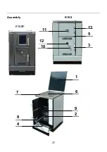
Страница 4: ...4 Geräteaufbau 1 9 2 6 4 8 7 13 5 3 10 12 11 K158F K158 ...
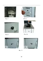
Страница 25: ...25 Bild 8 Bild 7 Bild 9 Bild 10 a b Bild 11 ...
Страница 26: ...26 Bild 12 Bild 13 Bild 14 Bild 15 Bild 16 Bild 17 ...
Страница 27: ...27 Bild 19 Bild 18 Bild 20 ...
Страница 29: ...29 Bild 29 Bild 30 Bild 33 Bild 31 Bild 32 Bild 35 Bild 36 Bild 34 ...
Страница 32: ...32 ...
Страница 33: ...33 ...
Страница 34: ...34 ...
Страница 37: ...37 Assembly K158 1 9 2 6 4 8 7 13 5 3 10 12 11 K158F ...
Страница 56: ...56 Pic 8 Pic 7 Pic 9 Pic 10 a b Pic 11 ...
Страница 57: ...____________________________________________________________ 57 Pic 12 Pic 13 Pic 14 Pic 15 Pic 16 Pic 17 ...
Страница 58: ...____________________________________________________________ 58 Pic 19 Pic 18 Pic 20 ...
Страница 59: ...59 Pic 23 Pic 24 Pic 25 Pic 26 Pic 27 Pic 28 ...
Страница 65: ...65 Structure de l appareil K158 K158F 1 9 2 6 4 8 7 13 5 3 10 12 11 ...
Страница 81: ...81 fig 8 fig 7 fig 9 fig 10 a b fig 11 ...
Страница 82: ...82 fig 12 fig 13 fig 14 fig 15 fig 16 fig 17 ...
Страница 83: ...83 fig 19 fig 18 fig 20 ...
Страница 84: ...84 fig 23 fig 24 fig 25 fig 26 fig 27 fig 28 ...
Страница 85: ...85 fig 30 fig 35 fig 36 fig 34 fig 29 fig 33 fig 31 fig 32 ...
Страница 90: ...90 Struttura dell apparecchio K158 K158F 1 9 2 6 4 8 7 13 5 3 10 12 11 ...
Страница 111: ...111 fig 8 fig 7 fig 9 fig 10 a b fig 11 ...
Страница 112: ...112 fig 12 fig 13 fig 14 fig 15 fig 16 fig 17 ...
Страница 113: ...113 fig 19 fig 18 fig 20 ...
Страница 114: ...114 fig 23 fig 24 fig 25 fig 26 fig 27 fig 28 ...
Страница 115: ...115 fig 33 fig 35 fig 36 fig 34 fig 29 fig 30 fig 31 fig 32 ...
Страница 118: ......
Страница 119: ...119 ...


