background image

Foreword

BXM32, BXM42

3-point Hitch Chipper-Shredder

2

1.  Foreword

1.1  Introduction

Congratulations on your choice of a Wallenstein 

BXM Series 

3-point Hitch Chipper-Shredder!

Wallenstein BXM Series Chipper-Shredders are designed to 
chip and chop small trees, brush, and other wood debris. The 

chipped / shredded material is fine enough to be composted or 

used in a variety of ways.

This manual covers the BXM Series models: 

•  BXM32
•  BXM42

Safe, efficient and trouble-free operation of this Wallenstein 

product requires that anyone using or servicing the machine 
reads the Safety, Operation, Maintenance information contained 
within this Operator's Manual.

Keep this manual handy for frequent reference and to pass on 
to new operators or owners. Call your Wallenstein dealer or 
the distributor if you need assistance, information or additional 
copies of the manuals.

Units of measurement in Wallenstein Equipment technical 
manuals are written as:  
US Customary (SI metric)

Wallenstein Equipment Inc. • © 2020

 WARNING!

Do not attempt to start or operate the machine 

without thoroughly reviewing this manual for 

safe and proper operation.
Always keep this manual with the machine.

W034

 www.wallensteinequipment.com

Содержание BXM Series

Страница 1: ...OPERATOR S MANUAL 3PHChipper Shredder BXM Series Document Number Z97053_En Rev Jan 2020 ...

Страница 2: ...roduct requires that anyone using or servicing the machine reads the Safety Operation Maintenance information contained within this Operator s Manual Keep this manual handy for frequent reference and to pass on to new operators or owners Call your Wallenstein dealer or the distributor if you need assistance information or additional copies of the manuals Units of measurement in Wallenstein Equipme...

Страница 3: ...TO Shaft Installing 26 6 Controls 27 6 1 PTO Control 27 6 2 Discharge Chute 27 6 3 Discharge Chute Deflector 27 6 4 Shredder Feed Gate Lever 27 6 5 Chipper Feed Hopper 28 7 Operating Instructions 29 7 1 Pre operation Checklist 30 7 2 Before Startup 30 7 3 Chipping Operation 31 7 4 Shredder Operation 32 7 5 Stopping Procedure 32 7 6 Stopping in an Emergency 32 7 7 Clearing a Plugged Chipper 33 7 8 ...

Страница 4: ... Province ZIP Postal Code Phone Number Contact Name Model Serial Number Delivery date I have thoroughly instructed the buyer on the equipment care adjustments safe operation and applicable warranty policy and reviewed the manuals Dealer Address City State Province ZIP Postal Code Phone Number 1 2 1 Dealer Inspection Report Check Blade Clearance and Rotor Turns Freely Check cutting blades twig brea...

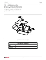
Страница 5: ...enstein product when ordering parts or requesting service or other information The Serial Number Plate location is shown in the illustration Please record the product Model and Serial Number in the space provided below for future reference Fig 1 Serial Number Plate Location Typical Record Product Information Here Model Serial Number ...

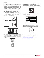
Страница 6: ...nd and can vary in the number of panels This type of decal provides additional information to the operator or explains the operation of a control Product Decals indicate machine model and serial number and other important information VIN NLV MODEL Manufactured by Wallenstein Equipment Inc 7201 Line 86 Wallenstein ON N0B2S0 Canada TYPE OF VEHICLE TYPE DE VEHICLE TRA REM GAWR PNBE KG GVWR PNBV KG DI...

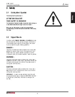
Страница 7: ...elines DANGER Indicates an imminently hazardous situation that if not avoided will result in death or serious injury This signal word is to be limited to the most extreme situations typically for machine components which for functional purposes cannot be guarded WARNING Indicates a potentially hazardous situation that if not avoided could result in death or serious injury and includes hazards that...

Страница 8: ...ructions to operate the machine An untrained operator is not qualified and exposes himself and bystanders to possible serious injury or death It is the owner s responsibility to the operator to ensure familiarity and understanding of the machine DO NOT allow riders during transport DO NOT risk injury or death by ignoring good safety practices 2 5 Equipment Safety Guidelines Safety is one of the ma...

Страница 9: ...rior to using every operator reads and understands the owner s manual is instructed in safe and proper use of the equipment understands and knows how to perform the Safe Condition procedure 2 8 Being Prepared Never use the machine until the operators have been adequately trained in the safe operation of the machine and have read and completely understand safety operation and feature sections of th...

Страница 10: ...that can result in failure and potential accidents Always remove paint from areas to be welded Heated paint gives of poisonous gases Therefore paint must be removed from an area with a radius of at least 4 10 cm before carrying out welding grinding or gas cutting In addition to the health hazard the weld is of inferior quality and strength if the paint is not removed Methods and precautionary meas...

Страница 11: ...ining the sign off sheet provided below can be used Make periodic reviews of Safety and Operation a standard practice for all operators Review again at the startup of every season The design and manufacture of this product conforms to relative provisions in the following standards ISO 4254 1 Agricultural machinery Safety ASABE S318 Safety for Agricultural Field Equipment ISO 3600 Operator s Manual...

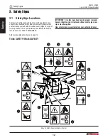
Страница 12: ... the various safety signs the type of warning and the area or particular function related to that area that requires your SAFETY AWARENESS Safety sign explanations begin on page 14 Think SAFETY Work SAFELY IMPORTANT If safety signs have been damaged removed become illegible or parts replaced without safety signs new signs must be applied New safety signs are available from your authorized dealer F...

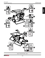
Страница 13: ...Safety 13 BXM32 BXM42 3 point Hitch Chipper Shredder Safety Signs 00887 2 2 5 8 10 11 12 13 9 3 Fig 3 Safety Decal Locations Typical ...

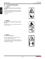
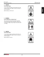
Страница 14: ...d bolted in place for operation BXM42 only 2 WARNING Risk of fingers being severed or serious injury to hands in this area Keep hands and feet out of inlet and discharge openings while machine is operating 3 CAUTION Risk of injury from flying debris Stay clear of material discharge chute Machine can expel wood chips fast enough to cause injury Do not point discharge at people animals or buildings ...

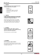
Страница 15: ...d also result 5 WARNING Risk of entanglement in rotating drive line Stay clear of the PTO shaft when the chipper is operating Do not operate chipper with PTO shaft cover removed Keep hands loose clothing and long hair away from drive line while it is rotating 6 CAUTION Risk of personal injury Do not overload the chipper by placing material into the feed hopper larger than the size stated on the de...

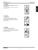
Страница 16: ... at close distances Always wear hearing protection when near the operating machine Noise exposure over 85 dB on a long term basis can cause severe hearing loss Exposure over 90 dB over a long term basis may cause permanent total hearing loss 9 WARNING Refer to the operator s manual Read ALL operating instructions in the manual Learn the meaning of ALL safety signs on the machine before operating i...

Страница 17: ...arrow 12 WARNING Risk of personal injury Stop the machine and disconnect the PTO shaft before performing any repair or maintenance procedure Place the machine in a state that makes it safe to work on See Safe Condition on page 7 13 WARNING Risk of serious injury if caught in drivebelt Never operate the machine with guard cover removed Always keep guards and covers in place when machine is in opera...

Страница 18: ... area must be clean and dry Make sure the surface is free of grease or oil Ambient temperature must be above 50 F 10 C NOTE Determine exact position before removing the backing paper on the decal 1 Peel the decal off the backing sheet 2 Align the decal with an edge on the machine if possible 3 Starting on one edge carefully press the center of the exposed sticky backing in place smoothing it out a...

Страница 19: ...rs are not qualified to use the machine Many features incorporated into this machine are the result of suggestions made by customers like you Read this manual carefully to learn how to use the chipper safely and provide maximum efficiency By following these instructions in conjunction with a good maintenance program your BXM Chipper Shredder can provide many years of trouble free service 4 2 Opera...

Страница 20: ... Fig 5 Components 1 Chipper Feed Hopper 2 Shredder Feed Hopper 3 Shredder Feed Gate Lever 4 Upper Rotor Housing 5 Belt Guard 6 Toplink Attach Point 7 Bottom Link Attach Point 8 PTO shaft 9 Operator s Manual Tube 10 Ledger Blade 11 Twig Breaker BXM42 only 12 Chop Block 13 Discharge Chute Lock Lever 14 Discharge Chute 15 Deflector Hood 16 Shredder Gate ...

Страница 21: ...BXM32 BXM42 3 point Hitch Chipper Shredder Familiarization 21 Fig 6 Components Typical 1 Shredder Knives 2 Rotor 3 Rotor Knife 4 Rotor Paddles 5 Drive Belts PTO Sheave 00894 2 3 4 1 5 ...

Страница 22: ...the implement from side to side 2 When reversing lower raise the lift arms so that they are level with the lower attachment points on the chipper 00895 Fig 7 Back up in line with the chipper 3 Back up slowly and align the balls in the lift arms to the pins on the chipper 4 Apply the tractor park brake 5 Starting on one side push the floating ball on the tractor s lift arms over the lower attachmen...

Страница 23: ...es in the manual and follow all safety signs on the machine CAUTION Wear suitable eye protection when cutting steel tubes 1 Remove the PTO shaft and mount the attachment on the tractor three point hitch 2 Start the tractor and raise the three point hitch up off the ground until the machine s input shaft is level with the tractor PTO output shaft This is the shortest distance between the input and ...

Страница 24: ...of the plastic tube with the end of the steel shaft 00943 Fig 14 Marking steel tube 10 Cut the steel tube off at the mark 11 Repeat this process for BOTH PTO shaft halves Use the cut off length of plastic tube to mark the remaining cuts Place the end of the steel shaft to be cut off in a vice so it is easier to control your cut 12 Remove the burrs from the edges of the steel shaft that were cut Cl...

Страница 25: ...ract 2 inches 50 mm from this measurement Call this measurement B L 2 50 mm B 00944 L Fig 17 Measurement B 4 If the collapsed length A is longer than measurement B from Step 3 the PTO shaft must be shortened 5 Subtract B from the uncut PTO shaft measurement A A B The result is how much BOTH halves of the PTO shaft need to be shortened Call this value C A B C 00945 A B L 2 inches L 50 mm Fig 18 C C...

Страница 26: ...nd onto the input PTO Connect the safety chain to the implement so that the shielding does not turn during operation 00866 Fig 20 Locking Pin Button 2 Slide out the end of the PTO shaft up to the tractor output PTO aligning the two shaft splines Press the locking pin button and push the shaft end onto output PTO 3 Once started slide the shaft all the way on You might hear a click and your button s...

Страница 27: ...ging PTO brake 6 2 Discharge Chute CAUTION Risk of injury from ejected wood chips Chipper rotor can expel wood chips fast enough to cause injury or damage Direct chute discharge away from work area people animals and objects W024 The discharge chute has a spring loaded latch handle that allows the chute to be positioned at any angle then locked into position with the latch 1 Lift the latch handle ...

Страница 28: ...and feet out of inlet and discharge openings while machine is operating W061 WARNING Risk of hands or feet being severed or seriously injured in this area Never operate the chipper with the feed hopper raised in the transport position Chipper feed hopper must be lowered and bolted in place for operation BXM42 only W060 Wood material is slid into the feed hopper past the safety curtain and into the...

Страница 29: ...or buildings Rotor can expel wood chips fast enough to cause injury Be aware of the size and shape of the material crotchety branches and logs can move in unpredictable ways and could cause injuries Large curved pieces should be cut to smaller straighter sections Do not work alone it is safer to work in pairs in case an emergency arises Never stand sit or climb onto any part of the chipper while i...

Страница 30: ...nt for personal protection is available and being used Check that jewelry loose fitting clothing are not worn Make sure long hair is tied back 7 2 Before Startup 1 Review Operating Safety Rules 2 Clear the area of all bystanders especially children 3 Make sure each operator is trained and familiar with the set up and operation of the wood chipper 4 Perform the Pre operation Checklist 5 Place the c...

Страница 31: ...aterial is drawn in as it engages 00902 Fig 27 Chipping wood 3 Make sure the wood chip pile is contained and does not affect the immediate work area Tip Be aware of the size and shape of the material Delimb large branches Crotchety curved branches can move in unpredictable ways Large curved pieces should be cut to smaller straighter sections Hold small diameter branches limbs together in a bundle ...

Страница 32: ...a stick or branch to push any piece of material in that does not move on its own and stops in the chipper housing Release the handle to close the gate Always make sure the gate is closed between loads to keep flying material contained within the shredder housing Do not prop the gate open 00903 Fig 28 Shredder feed Lever Control Lever 7 5 Stopping Procedure 1 Stop feeding material into the chipper ...

Страница 33: ...rge hood Use a stick to loosen any material jammed inside Do not leave anything in this area 5 Visually inspect to make sure nothing is jammed or wedged in the rotor Try restarting to see if the jam is cleared If the chipper is still plugged the jammed material must be removed by hand CAUTION Be aware Rotor continues to turn for a few revolutions after the PTO is disengaged Wait for all parts to s...

Страница 34: ...gh conditions or cornering 7 8 1 Prepare for Transport 1 Clean all dirt debris off the chipper Falling debris could cause problems for other traffic 2 Make sure all access covers are secured in place and the rotor upper housing is bolted down 3 Turn the discharge hood inward to reduce the width of the machine NOTE On BXM42 models the feed hopper can be rotated up to additionally reduce the width o...

Страница 35: ...e Replace Rotor may be bent Check for rotor wobble Replace rotor Rotor bearings failed Replace Loose fasteners Tighten See torque tables page 48 Machine requires excessive power or stalls Obstructed discharge Clear debris from discharge chute Engaging PTO too quickly Engage PTO at low engine speed then slowly increase Make sure hoppers and rotor housing are clear Feeding material too quickly Feed ...

Страница 36: ...t any unnecessary down time at the beginning of the next season 2 Inspect all rotating parts and remove entangled material 3 Thoroughly wash the machine to remove all dirt mud or debris 4 Run the machine a few minutes to dry the moisture from inside the machine 5 Touch up all paint nicks and scratches to prevent rusting 6 If not possible to store the machine inside cover with a waterproof tarp 7 S...

Страница 37: ...sure all covers and shields are reinstalled When cleaning any parts do not use gasoline or diesel fuel Use a regular cleanser Always use proper tools in good condition IMPORTANT If welding on the chipper is necessary protect sensitive tractor electronics by unhooking the chipper beforehand Always connect the ground clamp as close to the work area as possible WARNING Risk of serious personal injury...

Страница 38: ...Check ledger knife sharpness See page 42 Check twig breaker See page 41 Grease PTO Shaft Shield See page 39 Every 100 hours or Annually Check drive belt tension See page 44 Grease Rotor PTO bearings See page 37 9 3 Grease Points IMPORTANT Use a hand held grease gun for all greasing Pump one shot of grease per fitting Wipe grease fitting with a clean cloth before greasing to avoid injecting dirt an...

Страница 39: ...cation Every 50 hours of operation 3 PTO Shaft Shield 00909 3 3 Fig 34 Grease Points 50 Hours of Operation Location Every 100 hours of operation or annually 4 Rotor PTO Bearings 5 Rotor Bearings 00913 4 4 Fig 35 BXM32 Rotor PTO Bearings 00912 5 5 Fig 36 BXM32 Rotor Bearings ...

Страница 40: ...it is designed to stay stationary as the driveshaft turns Annual disassembly cleaning and inspection is recommended to make sure that all components function as intended Shear Pin The PTO shaft has a shear pin on the implement end at the input yoke The shear pin is designed to break in the event the drive system is overloaded to protect other critical components 00870 Fig 40 PTO Shear Pin The driv...

Страница 41: ...harpen the blades if the cutting edge becomes dull Check blade sharpness more often if processing material with a lot of sand soil or dirt in it Keeping the blades sharp reduces the amount of power required during operation If one blade needs to be sharpened or changed the opposite one should be done as well Sharpening Rotor Blades 1 Open the upper rotor housing CAUTION Risk of getting hands pinch...

Страница 42: ...e between the rotor blade and stationary ledger blade every 50 hours 9 7 1 Ledger Knife Clearance Use the ledger setting gauge to check knife clearance The thickness of the gauge is the correct ledger blade clearance If spacing is in excess of the gauge thickness adjust the clearance Checking 1 Open the upper rotor housing CAUTION Risk of getting hands pinched or wedged between lower rotor housing...

Страница 43: ...per housing 2 Rotate the ledger knife or replace it with a new or sharpened knife 3 Hand tighten the bolts and verify clearance setting 4 Tighten the bolts to torque value shown on page 48 IMPORTANT Make sure the ledger knife is installed squarely Both ends must protrude past the support the same amount 9 8 Chop Block The Chop Block is bolted in the bottom end of the upper rotor housing As shredde...

Страница 44: ... catching the knives and spacers as they become free 4 Change the knives to install in the other direction or replace with new or re sharpened knives 5 Ensure that the knives and spacers are installed in the correct sequence Improper installation decreases performance of the shredder Refer to illustration 6 Tighten down bolts as specified in the torque chart Make sure knives can rotate freely 7 Re...

Страница 45: ...heaves aligned with a laser alignment tool Contact your dealer for more information Sheave alignment can be checked using a straight edge One of at least 30 76 cm in length is required To check the alignment with a straight edge follow this procedure 1 Remove the belt guard 2 Place the straight edge along the face of the PTO sheave and place the opposite end along the face of the rotor sheave 3 Ch...

Страница 46: ...he three hex bolts on the bushing Thread them into the tapped holes on the bushing 3 Tighten each hex bolt progressively 1 4 turn until bushing is free from the sheave taper 4 Move the sheave to the required position to align the belt 5 Align drilled holes with tapped holes on the sheave Replace and hand tighten bolts 6 Tighten the set screw and recheck alignment 7 Carefully tighten hex bolts unif...

Страница 47: ... 2 5 cm 2 5 cm Shredder Hopper Opening 30 x 28 71 cm x 76 cm 40 x 33 102 cm x 84 cm Shredder Housing Opening 10 x 10 25 cm x 25 cm 11 x 11 27 cm x 27 cm Quantity of Shredder Knives 27 30 Rotor Weight 70 lb 32 kg 170 lb 77 kg Mounting System 3 point hitch CAT I iMatch Quick Hitch compatible Operating Weight 445 lb 202 kg 800 lb 363 kg Dimensions LxWxH 54 x 36 x 60 137 cm x 91 cm x 152 cm 72 x 44 x ...

Страница 48: ... locker increase torque values by 5 NOTE Bolt grades are identified by their head markings Imperial Bolt Torque Specifications Bolt Diameter Torque Value SAE Gr 2 SAE Gr 5 SAE Gr 8 lbf ft N m lbf ft N m lbf ft N m 1 4 6 8 9 12 12 17 5 16 10 13 19 25 27 36 3 8 20 27 33 45 45 63 7 16 30 41 53 72 75 100 1 2 45 61 80 110 115 155 9 16 60 95 115 155 165 220 5 8 95 128 160 215 220 305 3 4 165 225 290 390...

Страница 49: ...al purchase receipt with any claim This warranty does not cover the following 1 Normal maintenance or adjustments 2 Normal replacement of wearable and service parts 3 Consequential damage indirect damage or loss of profits 4 Damages resulting from Misuse negligence accident theft or fire Use of improper or insufficient fuel fluids or lubricants Use of parts or aftermarket accessories other than ge...

Страница 50: ...edder Operation 32 Stopping 32 Stopping in an Emergency 32 Transporting 34 Unplugging the Chipper 33 P Personal Protective Equipment PPE 8 Placing Chipper in Storage 36 Placing Feed Table in Stowed Position 34 Pre Operation Checklist 30 Prepare for Transport 34 PTO Shaft Installing 26 PTO Shaft Sizing 23 PTO Shear Pin 40 R Replacing Damaged Safety Signs 18 Rotor Blades 41 Sharpening 41 S Safe Cond...

Страница 51: ... Specifications 47 Stopping in an Emergency 32 Stopping Procedure 32 Storage 36 Placing Chipper in Storage 36 Removing from Storage 36 T Three point Hitch Connecting 22 Transporting 34 Prepare for Transport 34 Troubleshooting 35 Twig Breaker 41 U Unplugging the chipper 33 W Warranty 49 Welding on the Chipper 37 Welding Safety 10 ...

Страница 52: ...www wallensteinequipment com ...

Отзывы: