


370 I/O Modules
WAGO-I/O-SYSTEM 750
750-882 Media Redundancy ETHERNET Controller
Manual
1.5.0
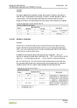
13.3.1.3 2 Channel Digital Input Module with Diagnostics
750-419, -421, -424, -425,
753-421, -424, -425
Table 421: 2 Channel Digital Input Module with Diagnostics
Input Process Image
Bit 7
Bit 6
Bit 5
Bit 4
Bit 3
Bit 2
Bit 1
Bit 0
Diagnostic
bit S 2
Channel 2
Diagnostic
bit S 1
Channel 1
Data bit
DI 2
Channel 2
Data bit
DI 1
Channel 1
The input modules seize 4 Instances in Class (0x65).
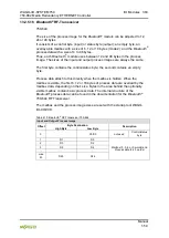
13.3.1.4 2 Channel Digital Input Module with Diagnostics and Output Process
Data
750-418,
753-418
The digital input module supplies a diagnostic and acknowledge bit for each input
channel. If a fault condition occurs, the diagnostic bit is set. After the fault
condition is cleared, an acknowledge bit must be set to re-activate the input. The
diagnostic data and input data bit is mapped in the Input Process Image, while
the acknowledge bit is in the Output Process Image.
Table 422: 2 Channel Digital Input Module with Diagnostics and Output Process Data
Input Process Image
Bit 7
Bit 6
Bit 5
Bit 4
Bit 3
Bit 2
Bit 1
Bit 0
Diagnostic bit
S 2
Channel 2
Diagnostic bit
S 1
Channel 1
Data bit
DI 2
Channel 2
Data bit
DI 1
Channel 1
The input modules seize 4 Instances in Class (0x65).
Output Process Image
Bit 7
Bit 6
Bit 5
Bit 4
Bit 3
Bit 2
Bit 1
Bit 0
Acknowledge-
ment bit Q 2
Channel 2
Acknowledge-
ment bit Q 1
Channel 1
0
0
And the input modules seize 4 Instances in Class (0x66).