


WAGO-I/O-SYSTEM 750
I/O Modules 369
750-882 Media Redundancy ETHERNET Controller
Manual
1.5.0
13.3.1 Digital Input Modules
Digital input modules supply one bit of data per channel to specify the signal
state for the corresponding channel. These bits are mapped into the Input
Process Image.
Some digital I/O modules have an additional diagnostic bit per channel in the
input process image. The diagnostic bit detects faults (e.g., wire breakage,
overloads and/or short circuits). For some I/O modules, the data bits also have
be evaluated with the set diagnostic bit.
When analog input modules are also present in the node, the digital data is
always appended after the analog data in the Input Process Image, grouped into
bytes.
1 sub index is assigned for each 8 bit.
Each input channel seizes one Instance in the Discrete Input Point Object (Class
0x65).
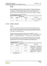
13.3.1.1 1 Channel Digital Input Module with Diagnostics
750-435
Table 419: 1 Channel Digital Input Module with Diagnostics
Input Process Image
Bit 7
Bit 6
Bit 5
Bit 4
Bit 3
Bit 2
Bit 1
Bit 0
Diagnostic
bit
S 1
Data bit
DI 1
The input modules seize 2 Instances in Class (0x65).
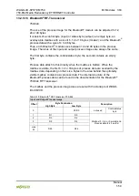
13.3.1.2 2 Channel Digital Input Modules
750-400, -401, -405, -406, -410, -411, -412, -427, -438, (and all variations),
753-400, -401, -405, -406, -410, -411, -412, -427
Table 420: 2 Channel Digital Input Modules
Input Process Image
Bit 7
Bit 6
Bit 5
Bit 4
Bit 3
Bit 2
Bit 1
Bit 0
Data bit
DI 2
Channel 2
Data bit
DI 1
Channel 1
The input modules seize 2 Instances in Class (0x65).